Community project
ESP32 OLED Snake Game
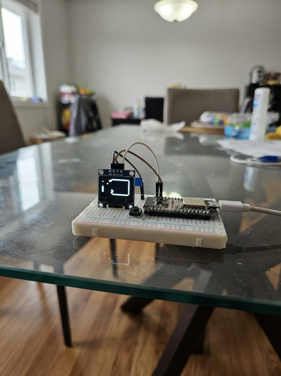
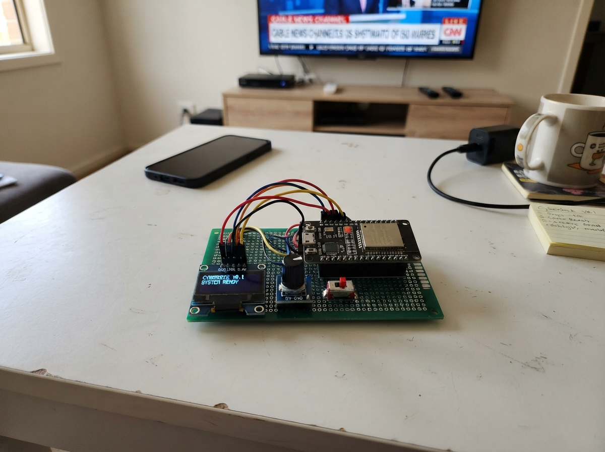
Build a playable Snake game on an ESP32 microcontroller with a small OLED display and two push buttons for control. This project combines hardware wiring, game logic, and real-time rendering to create a classic arcade experience in a compact form factor.
This guide provides a complete parts list, wiring diagram showing OLED and button connections, and the full firmware source code ready to upload. Follow the step-by-step assembly instructions to connect the SSD1306 display via I2C and wire the directional control buttons, then verify everything works with the included test procedure.
Wiring diagram

Gather all the parts
Assemble it in 5 steps
1. Power-off wiring
Disconnect the ESP32 from USB before making connections. Use a shared ground for the display and both buttons.
- The OLED and buttons must share ESP32 GND.
- Do not feed 5 V into an OLED module unless its board explicitly supports it; this project uses 3.3 V.
2. Connect the OLED
Connect OLED VCC to ESP32 3V3, GND to GND, SDA to GPIO21, and SCL to GPIO22. The firmware expects the normal SSD1306 I²C address 0x3C.
- Keep I²C leads short for reliable updates.
- Some visually identical OLEDs use an SH1106 controller or address 0x3D and will not work with this firmware unchanged.
3. Wire the left button
Connect one terminal of the normally-open left button to GPIO18 and the other terminal to GND. It uses the ESP32 internal pull-up, so no external resistor is needed.
- On a 4-leg tactile switch, use two legs on opposite sides of the switch, not two legs on the same internally connected side.
4. Wire the right button
Connect one terminal of the normally-open right button to GPIO19 and the other terminal to GND. It also uses the internal pull-up.
- Left/right choose menu items and rotate the snake. Hold both buttons to enter a selected menu item or pause/resume during play.
5. Power and verify
Reconnect USB power to the ESP32. The splash screen should appear, followed by the menu. Use Schematik’s Deploy button to compile and flash the project.
- If the OLED is blank, first recheck VCC/GND and the SDA/SCL pair.
- Do not hot-plug loose wires while the board is powered.
Review all connections
1. Connections between "oled_1" and "ESP32"
2. Connections between "button_left_1" and "ESP32"
3. Connections between "button_right_1" and "ESP32"
Deploy the firmware
#include <Arduino.h>
#include <Wire.h>
#include "Display.h"
#include "Input.h"
#include "Game.h"

constexpr uint8_t OLED_SDA = 21;
constexpr uint8_t OLED_SCL = 22;
constexpr uint8_t BUTTON_LEFT_PIN = 18;
constexpr uint8_t BUTTON_RIGHT_PIN = 19;

Display display(OLED_SDA, OLED_SCL);
Input input(BUTTON_LEFT_PIN, BUTTON_RIGHT_PIN);
Game game(display, input);

void setup() {
  Wire.begin(OLED_SDA, OLED_SCL);
  Wire.setClock(400000);
  input.begin();
  display.begin();
  game.begin();
}

void loop() {
  const uint32_t now = millis();
  input.update(now);
  game.update(now);
  game.render(now);
  yield();
}
Remix this project
Make it yours in one click
Open a full copy of this project in your own Schematik workspace — diagram, code, parts, and assembly steps included. Swap the sensor, add features, or redesign the whole thing with AI. The author's original stays untouched.