Community project
// // Nilm Whole-home Energy Metering Firmware /
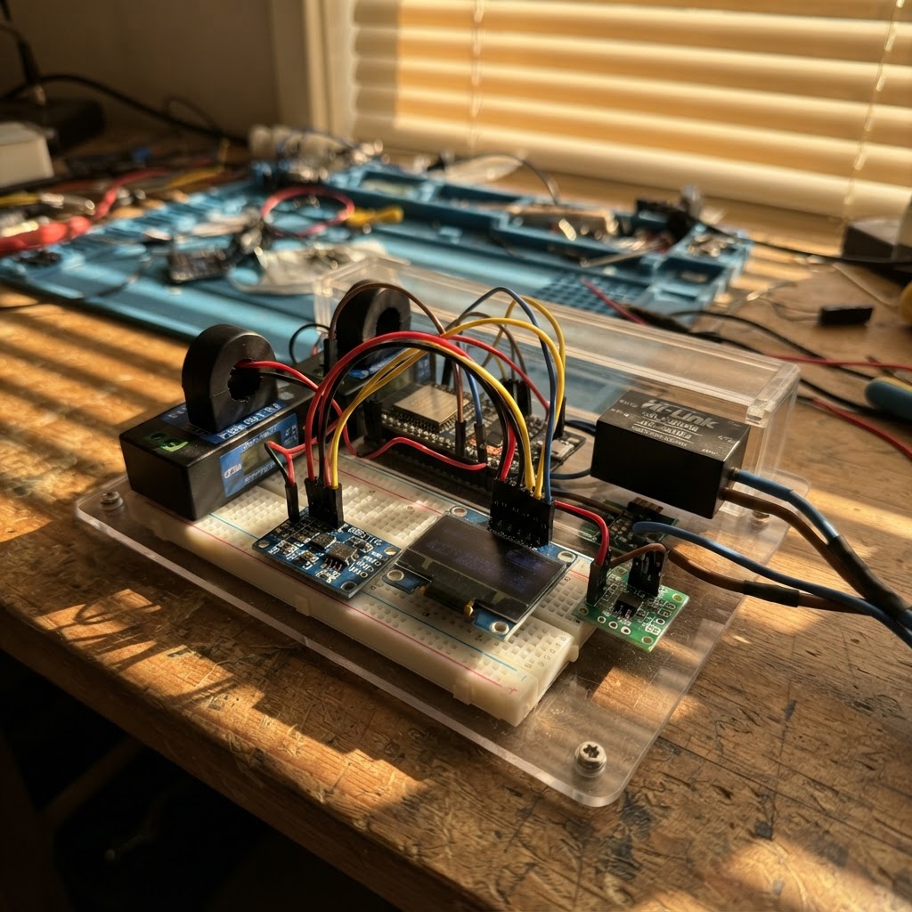
This guide builds a non-invasive whole-home energy meter using an ESP32, dual PZEM-004T energy sensors, and an ADS1115 ADC for high-resolution current sampling. The system monitors main and sub-circuit power consumption in real time, displaying live readings on an OLED screen while streaming data via MQTT to a local broker for logging and analysis.
The assembly covers safety-first mains isolation, DIN-rail mounting, non-invasive CT sensor placement, and firmware deployment. Readers will receive a complete wiring diagram, parts list, step-by-step assembly instructions, and pre-configured firmware that publishes JSON energy data (voltage, current, power, frequency) to MQTT topics compatible with home automation platforms and data visualization tools.
Wiring diagram

Gather all the parts
Assemble it in 10 steps
1. Safety first — isolate the mains
Turn off the main circuit breaker at the distribution board before doing ANY wiring. Verify zero voltage with a non-contact voltage tester on every terminal you will touch. Nepal 230V AC is lethal. Work with a qualified electrician for the mains connections (V+ / V- / L / N terminals).
- NEVER work on live mains.
- Double-check with a voltage tester before touching any terminal.
- All AC wiring to PZEM V+/V- and HiLink L/N must use rated 300V flex cable and insulated ferrule terminals.
2. Mount the enclosure and DIN-rail components
Use a plastic DIN-rail enclosure (at least IP20 for indoor panel use). Mount the Hi-Link HLK-5M05 PSU and the two PZEM-004T v3.0 modules on the DIN rail. Leave enough space for the ESP32 DevKit on a standoff or breadboard inside the enclosure.
- A 150×100×70 mm DIN rail enclosure with 2 DIN slots fits comfortably.
3. Wire 230V AC mains to Hi-Link PSU and PZEM voltage inputs
Using the main breaker still OFF: 1. Run a short 1.5mm² flex wire from the Live busbar to: Hi-Link L terminal, PZEM-1 V+ terminal, PZEM-2 V+ terminal (all in parallel via screw terminals or wago connectors). 2. Run Neutral busbar wire to: Hi-Link N terminal, PZEM-1 V- terminal, PZEM-2 V- terminal.
- Use only insulated 300V-rated wire for all AC connections.
- Ensure all screw terminals are fully tightened.
- PZEM modules MUST be connected to mains — the metering SoC is mains-powered; the 5V pin only powers the UART optocouplers.
4. Clamp CT sensors on live wires (Non-Invasive)
Open each CT clamp and snap it around the LIVE wire only (never enclose both live and neutral in the same clamp). - CT-1 (with pzem): clamp on the main incomer Live wire after the main breaker. - CT-2 (with pzem2): clamp on the live wire of a sub-circuit breaker you want to monitor. Connect each CT's 3.5mm jack to the PZEM CT screw terminals (CT+ / CT−). If your CT has bare wires, observe polarity: arrow on the CT points toward the load.
- CT clamp polarity determines the sign of current reading — if power reads negative or near-zero, flip the CT orientation.
- Clamp only the LIVE conductor, not Live+Neutral together.
5. Connect Hi-Link 5V output to the DC rail
From Hi-Link 5V_OUT terminal, run a wire to a small distribution block providing: - ESP32 DevKit VIN pin (5V in). - PZEM-1 5V pin. - PZEM-2 5V pin. From Hi-Link GND_OUT, run to a common GND strip shared by ESP32 GND, PZEM-1 GND, PZEM-2 GND, ADS1115 GND, OLED GND, and level-shifter GND.
- Use 0.5mm² wire for DC 5V runs inside the enclosure.
6. Wire the BSS138 logic level shifter
The level shifter bridges ESP32 (3.3V) UART to PZEM (5V) UART: 1. LV pin → 3.3V rail (ESP32 3V3 pin). 2. HV pin → 5V rail. 3. GND → common GND. 4. A1 (LV side) → ESP32 GPIO17 (TX2). 5. B1 (HV side) → PZEM-1 RX AND PZEM-2 RX (both in parallel on the same Modbus bus). 6. A2 (LV side) → ESP32 GPIO16 (RX2). 7. B2 (HV side) → PZEM-1 TX AND PZEM-2 TX (both in parallel).
- Both PZEMs share one Modbus RTU bus. PZEM-2 must be pre-programmed to address 0x02 (use the SetAddress sketch from PZEM004Tv30 library with ONLY PZEM-2 connected before parallel wiring).
7. Connect ADS1115 ADC module (I2C)
Wire the ADS1115 breakout: 1. VDD → 3.3V rail. 2. GND → GND rail. 3. SDA → ESP32 GPIO21 (shared I2C bus). 4. SCL → ESP32 GPIO22 (shared I2C bus). 5. ADDR → GND (sets I2C address 0x48). For each SCT-013-000 CT clamp connected to ADS1115: - Build a simple bias + burden circuit per channel: a 33Ω resistor across the CT output, plus two 10kΩ resistors from 3.3V to GND forming a 1.65V mid-rail bias, tied to AIN0 (and AIN1, AIN2 for additional channels).
- The ADS1115 adds high-frequency sampling capability for NILM event detection at 10+ Hz, complementing PZEM's 1Hz Modbus polling.
- Use twisted-pair wiring from CT output to ADS1115 input to minimise noise.
8. Connect SSD1306 OLED display
Wire the OLED: 1. VCC → 3.3V rail. 2. GND → GND rail. 3. SDA → ESP32 GPIO21 (shared I2C bus with ADS1115). 4. SCL → ESP32 GPIO22. Both OLED (0x3C) and ADS1115 (0x48) have different I2C addresses so they coexist on the same bus.
- Secure the OLED with double-sided tape or a 3D-printed bracket on the enclosure lid for easy viewing.
9. Edit firmware credentials, then deploy
Before deploying, open nilm_meter.ino and update: - WIFI_SSID and WIFI_PASSWORD for your local network. - MQTT_HOST with the IP address of your local Mosquitto broker PC. Then use Schematik's Deploy button to compile and flash the firmware to the ESP32.
- On the broker PC, run: mosquitto_sub -h localhost -t 'nilm/#' -v to verify JSON messages arriving every 2 seconds.
- For InfluxDB ingestion, use Node-RED MQTT-in → influxdb-out nodes, or a Telegraf MQTT consumer plugin.
10. Power on and verify
1. Restore the main circuit breaker. 2. The Hi-Link PSU will power up and the ESP32 will boot — OLED shows 'NILM Meter v1.0 / Booting...'. 3. Within 5–10 seconds the OLED updates with live V / A / W / kWh readings. 4. Check Serial Monitor (115200 baud via USB) for PZEM read confirmations and MQTT connection status. 5. Verify readings: voltage should be 220–235 V, frequency ~50 Hz.
- If PZEM reads 0.0V: confirm V+/V- are connected to mains and CT clamp is on the live wire.
- If MQTT shows 'FAILED': verify broker IP, ensure both ESP32 and broker PC are on the same LAN subnet.
- If OLED shows blank: check I2C address (try 0x3D instead of 0x3C on some modules).
Review all connections
1. Connections between "hislink_psu" and "ESP32"
2. Connections between "pzem" and "ESP32"
3. Connections between "pzem2" and "ESP32"
4. Connections between "level_shifter" and "ESP32"
5. Connections between "ads1115_1" and "ESP32"
6. Connections between "oled" and "ESP32"
Deploy the firmware
// ============================================================
//  NILM Whole-Home Energy Metering Firmware
//  Board   : ESP32 DevKit v1
//  Sensors : PZEM-004T v3.0 (main) + optional 2nd PZEM
//            ADS1115 (optional high-rate SCT-013 sampling)
//  Output  : MQTT JSON  →  local MQTT broker (e.g. Mosquitto)
//            or HTTP POST → InfluxDB / CSV endpoint
//  Display : SSD1306 128×64 OLED (live readout)
//  Grid    : 230 V / 50 Hz (Nepal NEC standard)
// ============================================================

#include <Arduino.h>
#include <Wire.h>
#include <WiFi.h>
#include <HardwareSerial.h>
#include <PZEM004Tv30.h>
#include <Adafruit_ADS1X15.h>
#include <Adafruit_GFX.h>
#include <Adafruit_SSD1306.h>
#include <PubSubClient.h>
#include <ArduinoJson.h>

// ── Pin Definitions ────────────────────────────────────────
#define PZEM_RX       16   // ESP32 RX2 ← PZEM TX (via level shifter A2 / B2)
#define PZEM_TX       17   // ESP32 TX2 → PZEM RX (via level shifter A1 / B1)
// I2C: SDA=GPIO21, SCL=GPIO22 (ESP32 defaults, shared by ADS1115 + OLED)

// ── WiFi Credentials ───────────────────────────────────────
#define WIFI_SSID     "YOUR_SSID"
#define WIFI_PASSWORD "YOUR_PASSWORD"

// ── MQTT Broker ────────────────────────────────────────────
#define MQTT_HOST     "192.168.1.100"   // IP of your local Mosquitto broker
#define MQTT_PORT     1883
#define MQTT_CLIENT   "nilm_meter_01"
#define MQTT_TOPIC_MAIN   "nilm/main/power"
#define MQTT_TOPIC_SUB    "nilm/sub/power"
#define MQTT_TOPIC_ADS    "nilm/ads/current"

// ── Sampling Intervals ─────────────────────────────────────
#define PZEM_INTERVAL_MS    2000   // PZEM poll: ~2 s (PZEM internal settling ≥1.2 s)
#define ADS_INTERVAL_MS     100    // ADS1115 high-rate sampling: 100 ms (10 Hz)
#define OLED_INTERVAL_MS    1000   // OLED refresh: 1 s

// ── OLED ───────────────────────────────────────────────────
#define SCREEN_W    128
#define SCREEN_H     64
#define OLED_ADDR   0x3C

// ── ADS1115 ────────────────────────────────────────────────
#define ADS_ADDR    0x48   // ADDR pin → GND
// SCT-013 burden resistor 33 Ω + 2×10 kΩ voltage divider bias at 1.65 V
// ADS1115 ±2.048 V range (PGA = 2), 16-bit → 0.0625 mV/LSB
// Current scale: SCT-013-030 = 30A/1V ↔ 30A over 1V across 33Ω? Actually
// SCT-013-000 (0-100A, 50mA secondary) → I_sec = I_pri / 2000
// V_burden = I_sec × 33Ω  → I_pri = V_ads / 33 × 2000   (adjust to your CT ratio)
#define SCT_TURNS_RATIO   2000    // SCT-013-000: 100A primary / 50mA secondary
#define SCT_BURDEN_OHM    33.0f
#define ADS_PGA_SCALE     0.0000625f  // V per LSB at PGA=±2.048V (2.048/32768)

// ── PZEM Modbus addresses ──────────────────────────────────
#define PZEM_ADDR_MAIN  0xF8   // default broadcast (single device)
#define PZEM_ADDR_SUB   0x02   // set via PZEM-004T-v30 SetAddress sketch first

// ══════════════════════════════════════════════════════════
//  Globals
// ══════════════════════════════════════════════════════════

struct PzemData {
    float voltage   = 0;
    float current   = 0;
    float power     = 0;
    float energy    = 0;
    float frequency = 0;
    float pf        = 0;
    bool  valid     = false;
};


// Forward declarations
void connectWifi();
void ensureMqtt();
void publishPzem(const char* topic, const PzemData& d, uint8_t addr);
void publishAds();
float measureAdsRms(uint8_t channel, uint16_t samples);
void updateOled();

HardwareSerial pzemSerial(2);
PZEM004Tv30    pzem_main(pzemSerial, PZEM_RX, PZEM_TX, PZEM_ADDR_MAIN);
PZEM004Tv30    pzem_sub (pzemSerial, PZEM_RX, PZEM_TX, PZEM_ADDR_SUB);

Adafruit_ADS1115 ads;
Adafruit_SSD1306 display(SCREEN_W, SCREEN_H, &Wire);

WiFiClient   wifiClient;
PubSubClient mqtt(wifiClient);

// Latest PZEM readings — main circuit

PzemData mainData, subData;

// ADS1115 RMS buffer (compute RMS over one cycle at 50 Hz)
static const uint16_t ADS_SAMPLES_PER_CYCLE = 20; // 10 Hz × 2 cycles gives some averaging
float adsRms[4] = {0, 0, 0, 0};

unsigned long lastPzemMs  = 0;
unsigned long lastAdsMs   = 0;
unsigned long lastOledMs  = 0;
unsigned long lastMqttMs  = 0;

// ══════════════════════════════════════════════════════════
//  Helper: connect WiFi
// ══════════════════════════════════════════════════════════
void connectWifi() {
    Serial.printf("Connecting to WiFi: %s\n", WIFI_SSID);
    WiFi.mode(WIFI_STA);
    WiFi.begin(WIFI_SSID, WIFI_PASSWORD);
    uint8_t attempts = 0;
    while (WiFi.status() != WL_CONNECTED && attempts < 30) {
        delay(500);
        Serial.print('.');
        attempts++;
    }
    if (WiFi.status() == WL_CONNECTED) {
        Serial.printf("\nWiFi connected. IP: %s\n", WiFi.localIP().toString().c_str());
    } else {
        Serial.println("\nWiFi FAILED — running in offline mode.");
    }
}

// ══════════════════════════════════════════════════════════
//  Helper: MQTT reconnect (non-blocking attempt)
// ══════════════════════════════════════════════════════════
void ensureMqtt() {
    if (WiFi.status() != WL_CONNECTED) return;
    if (mqtt.connected()) return;
    Serial.print("MQTT connecting...");
    if (mqtt.connect(MQTT_CLIENT)) {
        Serial.println(" OK");
    } else {
        Serial.printf(" FAILED rc=%d\n", mqtt.state());
    }
}

// ══════════════════════════════════════════════════════════
//  Helper: publish a PzemData struct as JSON
// ══════════════════════════════════════════════════════════
void publishPzem(const char* topic, const PzemData& d, uint8_t addr) {
    if (!mqtt.connected()) return;
    StaticJsonDocument<256> doc;
    doc["ts"]   = millis();           // ms uptime; replace with NTP epoch in production
    doc["addr"] = addr;
    doc["V"]    = d.voltage;
    doc["A"]    = d.current;
    doc["W"]    = d.power;
    doc["VAr"]  = d.power * (d.pf > 0.001f ? sqrtf(1.0f - d.pf * d.pf) / d.pf : 0);
    doc["PF"]   = d.pf;
    doc["Hz"]   = d.frequency;
    doc["kWh"]  = d.energy;
    doc["valid"]= d.valid;
    char buf[256];
    serializeJson(doc, buf, sizeof(buf));
    mqtt.publish(topic, buf);
}

// ══════════════════════════════════════════════════════════
//  Helper: publish ADS1115 RMS currents
// ══════════════════════════════════════════════════════════
void publishAds() {
    if (!mqtt.connected()) return;
    StaticJsonDocument<192> doc;
    doc["ts"] = millis();
    for (uint8_t ch = 0; ch < 4; ch++) {
        char key[8];
        snprintf(key, sizeof(key), "A_ch%u", ch);
        doc[key] = adsRms[ch];
    }
    char buf[192];
    serializeJson(doc, buf, sizeof(buf));
    mqtt.publish(MQTT_TOPIC_ADS, buf);
}

// ══════════════════════════════════════════════════════════
//  Helper: compute RMS current from ADS1115 channel
//  Accumulates SAMPLE_N readings, returns RMS amp value
// ══════════════════════════════════════════════════════════
float measureAdsRms(uint8_t channel, uint16_t samples) {
    ads.setGain(GAIN_TWO);  // ±2.048 V
    double sum = 0;
    for (uint16_t i = 0; i < samples; i++) {
        int16_t raw = ads.readADC_SingleEnded(channel);
        float v = raw * ADS_PGA_SCALE;
        // Remove DC bias (1.65 V mid-rail): subtract ~26400 raw (1.65/0.0000625)
        // We use AC coupling assumption: mean removal in sliding window not shown here
        // For simplicity, square and accumulate (bias cancels in differential config)
        sum += (double)v * v;
        delayMicroseconds(200); // ~5 kHz effective sample rate
    }
    float vrms = sqrtf((float)(sum / samples));
    // Convert V_rms → I_primary_rms
    return (vrms / SCT_BURDEN_OHM) * SCT_TURNS_RATIO;
}

// ══════════════════════════════════════════════════════════
//  OLED display update
// ══════════════════════════════════════════════════════════
void updateOled() {
    display.clearDisplay();
    display.setTextSize(1);
    display.setTextColor(SSD1306_WHITE);
    display.setCursor(0, 0);

    if (mainData.valid) {
        display.printf("V:%.1fV  Hz:%.1f\n", mainData.voltage, mainData.frequency);
        display.printf("I:%.2fA  PF:%.2f\n", mainData.current, mainData.pf);
        display.printf("P:%.1fW\n",          mainData.power);
        display.printf("E:%.3fkWh\n",        mainData.energy);
    } else {
        display.println("Main: No data");
    }

    display.drawLine(0, 34, 127, 34, SSD1306_WHITE);

    display.setCursor(0, 37);
    if (subData.valid) {
        display.printf("Sub %.1fW %.3fkWh\n", subData.power, subData.energy);
    } else {
        display.println("Sub: No data");
    }

    display.setCursor(0, 50);
    display.printf("WiFi:%s MQTT:%s",
        WiFi.status() == WL_CONNECTED ? "OK" : "--",
        mqtt.connected()               ? "OK" : "--");

    display.display();
}

// ══════════════════════════════════════════════════════════
//  Setup
// ══════════════════════════════════════════════════════════
void setup() {
    Serial.begin(115200);
    delay(500);
    Serial.println("\n=== NILM Energy Meter Booting ===");

    // I2C (SDA=21, SCL=22 — ESP32 defaults)
    Wire.begin(21, 22);

    // OLED
    if (!display.begin(SSD1306_SWITCHCAPVCC, OLED_ADDR)) {
        Serial.println("OLED init FAILED — continuing without display.");
    } else {
        display.clearDisplay();
        display.setTextSize(1);
        display.setTextColor(SSD1306_WHITE);
        display.setCursor(0, 0);
        display.println("NILM Meter v1.0");
        display.println("Booting...");
        display.display();
    }

    // ADS1115
    ads.setDataRate(RATE_ADS1115_860SPS);
    if (!ads.begin(ADS_ADDR)) {
        Serial.println("ADS1115 init FAILED — SCT-013 channels disabled.");
    } else {
        Serial.println("ADS1115 OK");
    }

    // PZEM UART2
    pzemSerial.begin(9600, SERIAL_8N1, PZEM_RX, PZEM_TX);
    delay(100);
    Serial.println("PZEM UART2 started.");

    // WiFi
    connectWifi();

    // MQTT
    mqtt.setServer(MQTT_HOST, MQTT_PORT);
    mqtt.setKeepAlive(30);
    mqtt.setSocketTimeout(5);
    ensureMqtt();

    Serial.println("Setup complete. Entering loop.");
}

// ══════════════════════════════════════════════════════════
//  Loop
// ══════════════════════════════════════════════════════════
void loop() {
    unsigned long now = millis();

    // 1. MQTT keep-alive
    if (WiFi.status() == WL_CONNECTED) {
        ensureMqtt();
        mqtt.loop();
    }

    // 2. Poll PZEM sensors every PZEM_INTERVAL_MS
    if (now - lastPzemMs >= PZEM_INTERVAL_MS) {
        lastPzemMs = now;

        // ── Main circuit ──────────────────────────────────
        mainData.voltage   = pzem_main.voltage();
        mainData.current   = pzem_main.current();
        mainData.power     = pzem_main.power();
        mainData.energy    = pzem_main.energy();
        mainData.frequency = pzem_main.frequency();
        mainData.pf        = pzem_main.pf();
        mainData.valid     = !isnan(mainData.voltage) && !isnan(mainData.current);

        if (mainData.valid) {
            Serial.printf("[MAIN] V=%.1f A=%.3f W=%.1f PF=%.2f Hz=%.1f kWh=%.3f\n",
                mainData.voltage, mainData.current, mainData.power,
                mainData.pf, mainData.frequency, mainData.energy);
            publishPzem(MQTT_TOPIC_MAIN, mainData, PZEM_ADDR_MAIN);
        } else {
            Serial.println("[MAIN] PZEM read error — check wiring and mains connection.");
        }

        // ── Sub-circuit (optional) ────────────────────────
        subData.voltage   = pzem_sub.voltage();
        subData.current   = pzem_sub.current();
        subData.power     = pzem_sub.power();
        subData.energy    = pzem_sub.energy();
        subData.frequency = pzem_sub.frequency();
        subData.pf        = pzem_sub.pf();
        subData.valid     = !isnan(subData.voltage) && !isnan(subData.current);

        if (subData.valid) {
            Serial.printf("[SUB]  V=%.1f A=%.3f W=%.1f PF=%.2f Hz=%.1f kWh=%.3f\n",
                subData.voltage, subData.current, subData.power,
                subData.pf, subData.frequency, subData.energy);
            publishPzem(MQTT_TOPIC_SUB, subData, PZEM_ADDR_SUB);
        }
        // No-error print for sub; it may simply be absent
    }

    // 3. ADS1115 high-rate RMS sampling every ADS_INTERVAL_MS
    if (now - lastAdsMs >= ADS_INTERVAL_MS) {
        lastAdsMs = now;
        // Sample each channel; 50 samples each at ~200µs → ~10 ms per channel
        for (uint8_t ch = 0; ch < 4; ch++) {
            adsRms[ch] = measureAdsRms(ch, 50);
        }
        publishAds();
    }

    // 4. OLED refresh every OLED_INTERVAL_MS
    if (now - lastOledMs >= OLED_INTERVAL_MS) {
        lastOledMs = now;
        updateOled();
    }

    // 5. WiFi reconnect watchdog (every 30 s)
    static unsigned long lastWifiCheck = 0;
    if (now - lastWifiCheck >= 30000) {
        lastWifiCheck = now;
        if (WiFi.status() != WL_CONNECTED) {
            Serial.println("WiFi lost — reconnecting...");
            WiFi.reconnect();
        }
    }
}
Remix this project
Make it yours in one click
Open a full copy of this project in your own Schematik workspace — diagram, code, parts, and assembly steps included. Swap the sensor, add features, or redesign the whole thing with AI. The author's original stays untouched.