Community project
Timed Bolt Lock Box
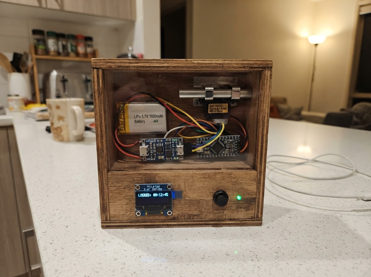
This project builds a time-locked storage box using an ESP32 microcontroller, a micro servo, and a small OLED display. The user sets a delay time (1–60 minutes) on the display, presses start to engage the lock, and the servo-driven bolt mechanism holds until the countdown expires and automatically unlocks.
The guide provides a complete wiring diagram, parts list, and step-by-step assembly instructions for the power chain (LiPo battery, TP4056 charger, MT3608 boost converter), SPI display connection, servo control, and mechanical bolt assembly. Firmware code is included to handle the state machine, button input, countdown timer, and servo actuation.
Wiring diagram

Gather all the parts
Assemble it in 7 steps
1. Gather and inspect all parts
Lay out: XIAO ESP32-C3, HiLetgo 0.42" SPI OLED, GOTECK 5g servo, TP4056 USB-C charger module, MT3608 boost converter, AKZYTUE 1000mAh LiPo (JST connector), and two 6×6mm tact buttons. Set the MakerHawk LiPo (PH1.25 connector) aside as a spare — the JST connector on the AKZYTUE matches TP4056 modules directly.
- Check JST polarity on the AKZYTUE battery before plugging in — red=positive, black=negative.
- Do NOT connect the LiPo to the TP4056 until after trimming the MT3608 boost converter.
- Never short LiPo terminals. Keep the battery away from metal tools.
2. Trim the MT3608 boost converter to 5.0V
Connect the MT3608 VIN and GND to a bench power supply or temporary 3.7V source (AA batteries work). Measure VOUT with a multimeter while slowly turning the onboard potentiometer clockwise until the output reads exactly 5.0V. Disconnect and mark the preset pot.
- Turn the pot very slowly — it is sensitive. Aim for 4.95–5.05V.
- If the pot spins freely with no output change, solder a jumper wire and retry.
- Do NOT connect the servo or XIAO to the boost output until it is confirmed at 5.0V. Over-voltage will damage the XIAO and OLED.
3. Wire the power chain
Solder the following connections: (1) AKZYTUE LiPo JST plug → TP4056 B+ and B- pads. (2) TP4056 OUT+ → MT3608 VIN. (3) TP4056 OUT- → MT3608 GND (common ground). (4) MT3608 VOUT → XIAO 5V pin. (5) MT3608 GND → XIAO GND. (6) MT3608 VOUT → servo red (VCC) wire. (7) Servo black (GND) wire → common GND.
- Run all GND connections to a single ground bus — a small piece of perfboard works well.
- The TP4056 USB-C port is now the charging port for the entire lockbox.
- Double-check polarity at every connection before applying power.
- The XIAO's onboard ETA4054 charger IC is bypassed in this design — do not also plug a LiPo into the XIAO BAT pads.
4. Wire the SPI OLED display
Connect the HiLetgo 0.42" SPI OLED (7 pins) to the XIAO as follows: • GND → GND rail • VCC → XIAO 3V3 pin • SCL (clock) → XIAO GPIO6 (D4) • SDA (data/MOSI) → XIAO GPIO7 (D5) • RES (reset) → XIAO GPIO3 (D1) • DC (data/cmd) → XIAO GPIO4 (D2) • CS (chip select) → XIAO GPIO10 (D10)
- The OLED runs on 3.3V only — do NOT connect VCC to the 5V rail.
- The 7-pin SPI module has labels silkscreened on the back. Match them carefully.
- Confirm interface is SPI — the HiLetgo module label should say SPI, not IIC. The SPI and I2C variants look identical but have different pin counts and solder bridge configurations.
5. Wire the servo signal and buttons
Servo signal: Connect servo orange/yellow wire → XIAO GPIO5 (D3). Buttons: each 6×6mm tact switch has 4 pins in 2 pairs. Connect one pair to GND, the other pair to the GPIO. Button UP: signal side → XIAO GPIO0 (D0). Button START: signal side → XIAO GPIO1 (D1 label on some boards, actually GPIO1).
- On the 6×6mm tact switch, pins 1&2 are shorted together, and pins 3&4 are shorted together. Bridge one pair to GND and the other to the GPIO — it doesn't matter which pair goes to which.
- Internal pull-ups are enabled in firmware — no external resistors needed.
6. First power-on test
Before closing the enclosure: plug a USB-C cable into the TP4056 module (not the XIAO). The red LED on the TP4056 should light while charging. Press Deploy in Schematik to flash the firmware. The OLED should display 'SET TIME' with '05:00'. Press the UP button to increment the minutes. Press the LOCK button to start the countdown and extend the servo arm.
- If the OLED is blank, check SCL/SDA/DC/CS wiring. The most common issue is DC and CS swapped.
- If the servo twitches but doesn't reach full angle, confirm the MT3608 is at 5.0V under load.
- Keep fingers clear of the servo and scotch-yoke mechanism during first test.
7. Mechanical assembly — scotch-yoke bolt mechanism
Print or fabricate: (1) A servo horn cam disk with an off-center pin (offset 4–6mm from center). (2) A slotted yoke bar that the pin rides in, connected to the bolt arms. (3) A housing that constrains the bolt to linear motion only. Mount the servo in the lockbox body. Attach the cam disk to the servo horn. Thread the yoke slot over the cam pin. Attach bolt arms to the yoke ends. Bolt travel should be 8–12mm. Adjust OPEN_ANGLE (10°) and LOCKED_ANGLE (170°) in firmware to match your printed geometry.
- PETG or ABS recommended for the yoke and bolt arms — PLA may creep under sustained load.
- Lubricate the cam pin and slot with a small amount of white lithium grease for smooth, quiet operation.
- Test the full travel range manually (by hand-rotating servo horn) before closing the box.
- Ensure the bolt arms cannot over-travel and bind the servo — this triggers stall current and may heat the motor over time, even with the GOTECK's stall protection.
Review all connections
1. Connections between "oled" and "ESP32"
2. Connections between "servo1" and "ESP32"
3. Connections between "btn_up" and "ESP32"
4. Connections between "btn_start" and "ESP32"
5. Connections between "lipo" and "ESP32"
6. Connections between "charger" and "ESP32"
7. Connections between "boost" and "ESP32"
Deploy the firmware
#include <Arduino.h>
#include <U8g2lib.h>
#include <SPI.h>
#include <ESP32Servo.h>

// ── Pin definitions ─────────────────────────────────────────────────────────
#define OLED_SCK    6
#define OLED_MOSI   7
#define OLED_CS    10
#define OLED_DC     4
#define OLED_RST    3
#define SERVO_PIN   5
#define BTN_UP      0
#define BTN_START   1

// ── Hardware objects ─────────────────────────────────────────────────────────
// U8g2 SW SPI: (rotation, SCK, MOSI, CS, DC, RST)

enum State { SET_TIME, LOCKING, COUNTDOWN, UNLOCKING };


// Forward declarations
bool btnUpPressed();
bool btnStartPressed();
bool upFired();
bool startFired();
void drawSetTime();
void drawCountdown();
void drawMessage(const char* line1, const char* line2);

U8G2_SSD1306_72X40_ER_1_4W_SW_SPI u8g2(
    U8G2_R0, OLED_SCK, OLED_MOSI, OLED_CS, OLED_DC, OLED_RST);

Servo lockServo;

// ── Config ───────────────────────────────────────────────────────────────────
static const int OPEN_ANGLE   = 10;   // servo angle = bolt retracted (unlocked)
static const int LOCKED_ANGLE = 170;  // servo angle = bolt extended (locked)
static const int MIN_MINUTES  = 1;
static const int MAX_MINUTES  = 60;

// ── State machine ────────────────────────────────────────────────────────────

State state = SET_TIME;

int     setMinutes    = 5;         // default 5 min
long    countdownSec  = 0;
unsigned long lastTick     = 0;    // millis of last 1-second tick
unsigned long lastUpPress  = 0;    // for button debounce / repeat
unsigned long lockHoldStart = 0;   // for emergency hold-to-cancel

// ── Button helpers ───────────────────────────────────────────────────────────
bool btnUpPressed()    { return digitalRead(BTN_UP)    == LOW; }
bool btnStartPressed() { return digitalRead(BTN_START) == LOW; }

// Debounce with auto-repeat for UP button (hold to scroll fast)
static unsigned long lastUpFire = 0;
static bool          upHeld     = false;
bool upFired() {
    if (!btnUpPressed()) { upHeld = false; return false; }
    unsigned long now = millis();
    if (!upHeld) {
        if (now - lastUpFire < 50) return false; // initial debounce
        upHeld = true; lastUpFire = now; return true;
    }
    // held: fire every 400 ms, then every 150 ms after 2 s
    unsigned long repeat = (now - lastUpFire > 2000) ? 150 : 400;
    if (now - lastUpFire >= repeat) { lastUpFire = now; return true; }
    return false;
}

// Debounce for START button (single-press)
static bool startWasDown = false;
bool startFired() {
    bool down = btnStartPressed();
    if (down && !startWasDown) { startWasDown = true; return true; }
    if (!down) startWasDown = false;
    return false;
}

// ── Display helpers ──────────────────────────────────────────────────────────
// 72x40 display; xOffset=30 maps GDDRAM 132-wide → visible 72 cols
static const int XO = 30;  // horizontal pixel offset for SSD1306 72x40

void drawSetTime() {
    char buf[12];
    u8g2.clearBuffer();

    // Title row
    u8g2.setFont(u8g2_font_5x7_tr);
    u8g2.setCursor(XO + 6, 8);
    u8g2.print("SET TIME");

    // Large minutes
    u8g2.setFont(u8g2_font_logisoso16_tr);
    snprintf(buf, sizeof(buf), "%02d:00", setMinutes);
    u8g2.setCursor(XO + 3, 28);
    u8g2.print(buf);

    // Help row
    u8g2.setFont(u8g2_font_5x7_tr);
    u8g2.setCursor(XO, 38);
    u8g2.print("^UP >LOCK");

    u8g2.sendBuffer();
}

void drawCountdown() {
    char buf[12];
    long s = countdownSec;
    int hh = s / 3600; s %= 3600;
    int mm = s / 60;
    int ss = s % 60;

    u8g2.clearBuffer();

    // Status row
    u8g2.setFont(u8g2_font_5x7_tr);
    u8g2.setCursor(XO + 2, 8);
    u8g2.print("*LOCKED*");

    // Countdown digits
    u8g2.setFont(u8g2_font_logisoso16_tr);
    if (hh > 0) {
        snprintf(buf, sizeof(buf), "%d:%02d", hh, mm);
    } else {
        snprintf(buf, sizeof(buf), "%02d:%02d", mm, ss);
    }
    u8g2.setCursor(XO + 2, 28);
    u8g2.print(buf);

    // Cancel hint
    u8g2.setFont(u8g2_font_5x7_tr);
    u8g2.setCursor(XO, 38);
    u8g2.print("hld>cncl");

    u8g2.sendBuffer();
}

void drawMessage(const char* line1, const char* line2) {
    u8g2.clearBuffer();
    u8g2.setFont(u8g2_font_5x7_tr);
    u8g2.setCursor(XO, 16);
    u8g2.print(line1);
    if (line2) {
        u8g2.setCursor(XO, 28);
        u8g2.print(line2);
    }
    u8g2.sendBuffer();
}

// ── Arduino entry points ─────────────────────────────────────────────────────
void setup() {
    pinMode(BTN_UP,    INPUT_PULLUP);
    pinMode(BTN_START, INPUT_PULLUP);

    // Servo – park at open position
    ESP32PWM::allocateTimer(0);
    lockServo.setPeriodHertz(50);
    lockServo.attach(SERVO_PIN, 500, 2400);
    lockServo.write(OPEN_ANGLE);

    // Display init
    u8g2.begin();
    u8g2.setContrast(255);

    drawSetTime();
}

void loop() {
    unsigned long now = millis();

    switch (state) {

    // ── SET TIME ─────────────────────────────────────────────────────────────
    case SET_TIME:
        if (upFired()) {
            setMinutes++;
            if (setMinutes > MAX_MINUTES) setMinutes = MIN_MINUTES;
            drawSetTime();
        }
        if (startFired()) {
            state = LOCKING;
            drawMessage("LOCKING", "...");
            lockServo.write(LOCKED_ANGLE);
            delay(800); // let servo travel
            countdownSec = (long)setMinutes * 60L;
            lastTick = millis();
            lockHoldStart = 0;
            state = COUNTDOWN;
            drawCountdown();
        }
        break;

    // ── COUNTDOWN ────────────────────────────────────────────────────────────
    case COUNTDOWN:
        // 1-second tick
        if (millis() - lastTick >= 1000) {
            lastTick += 1000;
            countdownSec--;
            if (countdownSec <= 0) {
                // Time's up — unlock
                state = UNLOCKING;
                drawMessage("TIME UP", "UNLOCKED");
                lockServo.write(OPEN_ANGLE);
                delay(800);
                state = SET_TIME;
                setMinutes = 5;
                drawSetTime();
            } else {
                drawCountdown();
            }
        }

        // Emergency cancel: hold START for 3 seconds
        if (btnStartPressed()) {
            if (lockHoldStart == 0) lockHoldStart = millis();
            if (millis() - lockHoldStart >= 3000) {
                state = UNLOCKING;
                drawMessage("CANCELLED", "UNLOCKED");
                lockServo.write(OPEN_ANGLE);
                delay(800);
                state = SET_TIME;
                setMinutes = 5;
                lockHoldStart = 0;
                drawSetTime();
            }
        } else {
            lockHoldStart = 0;
        }
        break;

    default:
        break;
    }
}
Remix this project
Make it yours in one click
Open a full copy of this project in your own Schematik workspace — diagram, code, parts, and assembly steps included. Swap the sensor, add features, or redesign the whole thing with AI. The author's original stays untouched.