Community project
Automated Roti Pressing and Cooking
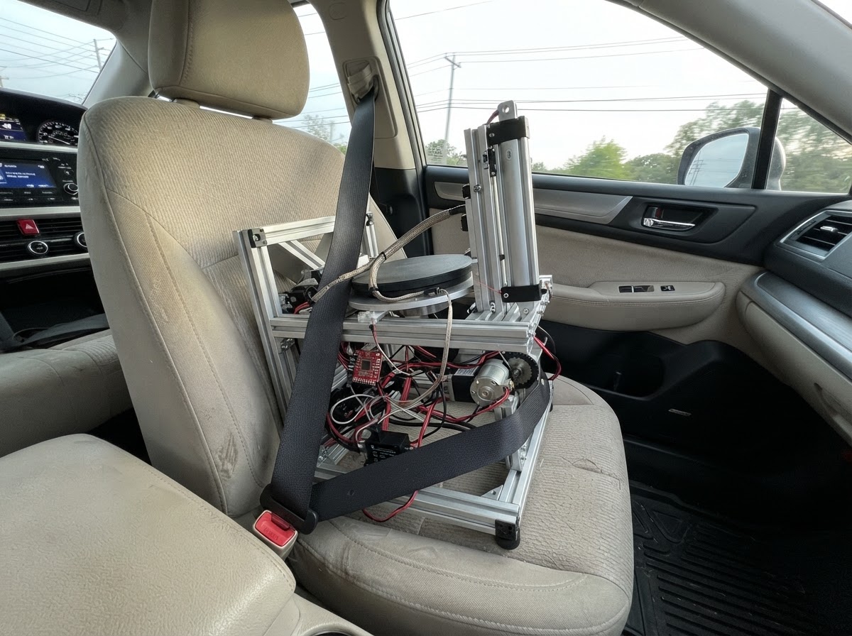
This guide builds an automated roti press that handles dough feeding, pressing, cooking, and ejection with precise temperature control. The system uses an ESP32 microcontroller to orchestrate multiple 24 V motors, monitor press position and dough presence, and maintain the heated press plate at the correct cooking temperature using a thermocouple sensor and solid-state relay.
Builders will receive a complete wiring diagram, parts list with sourcing guidance, safety-critical firmware with state machine control, and step-by-step assembly instructions covering food-contact fabrication, thermal protection integration, mains enclosure construction, and safe commissioning procedures before production use.
Wiring diagram

Gather all the parts
Assemble it in 6 steps
1. Fabricate the food-contact press and hopper
Have the qualified fabricator make two flat, parallel 200 mm cooking faces with a certified PFOA-free food-contact non-stick coating. Use a guided upper plate so it cannot tilt, set a fixed mechanical closing stop for about 2 mm roti thickness, and provide a removable covered food-safe hopper/chute that releases only one pre-portioned dough ball at a time. Use a food-safe silicone-edged ejector and removable collection tray.
- Target dough balls of roughly 35–45 g; final diameter, thickness, and cooking time must be tuned with the actual flour hydration.
- Make every food-contact part removable for washing; keep motors, grease, bearings, and wiring outside the food zone.
- Do not use loose flour dust as the anti-stick method inside the machine; specify the coating and a repeatable low-stick dough recipe instead.
- Do not use damaged, scratched, unknown, or unverified non-stick coating.
- The guide frame must prevent finger access to the closing gap; use a guard/interlock designed by the fabricator.
2. Fit heaters, sensing, and independent thermal protection
Mount the plate heaters as specified by the fabricator. Install the K-type probe in a blind hole close to the lower cooking surface, using thermal compound compatible with its temperature rating; it must not enter the food area. Fit a manual-reset 300 °C thermal cutoff directly on the hottest credible plate/heater location, in series with the contactor coil.
- Use a second independent temperature measurement during commissioning to calibrate the 225 °C firmware setpoint to actual plate temperature.
- Route thermocouple wire away from mains and motor wires; use a proper thermocouple extension connector where needed.
- The thermal cutoff and emergency stop must be hard-wired; they are not firmware-controlled.
- A qualified appliance electrician must choose the cutoff temperature and placement after measuring worst-case heater temperatures.
3. Build the earthed mains enclosure
A qualified appliance electrician must mount the fused IEC inlet, 2-pole safety contactor, SSR on its required heatsink, and both enclosed isolated power supplies in a metal, earthed, finger-safe enclosure. Bond protective earth continuously from the inlet to the metal chassis and both heated plates. Keep 230 VAC wiring physically segregated from the 24 V and 3.3 V control wiring.
- For 1200 W at 230 VAC, heater current is about 5.2 A; electrician must select approved wire, fuse, terminals, contactor and enclosure ratings with margin.
- Mount the SSR on a correctly sized aluminium heatsink and provide ventilation; verify its case temperature during a sustained heating run.
- Use strain relief at the mains inlet and cover all live terminals.
- 230 VAC can kill or start a fire. Do not build, test, or service the mains section while energized unless you are qualified to do so.
- Never rely on the SSR as the sole means of removing mains power: the 2-pole contactor and thermal/E-stop safety chain are mandatory.
4. Install 24 V motion hardware and guarded inputs
Wire the 24 V supply to the three motor drivers and isolated safety-input module. Connect each motor to its dedicated driver. Fit normally-closed open and close limit switches mechanically on the press motion, then route their isolated outputs to input-expander pins GPA4 and GPA5. Install the guard, start button, dough-present sensor, and emergency stop through the isolated input module; its separate normally-closed safety contact must be in series with the contactor coil.
- Measure each motor's real stall current and replace the provisional 24 V supply/driver ratings if needed before regular use.
- Verify physically that pressing E-stop removes contactor coil power and heater supply even with the ESP32 unplugged.
- Set the dough sensor so it detects the ball seated in the feed pocket, not dough higher in the hopper.
- Keep the mechanism de-energized while setting limit switches.
- The press must stop mechanically at the calibrated thickness even if a limit switch fails.
5. Connect the low-voltage controller
Power the ESP32 from the isolated 5 V supply. Wire MAX31855 to ESP32 GPIO 18 (SCK), GPIO 19 (SO), and GPIO 23 (CS). Wire the MCP23017 expander to GPIO 21 (SDA) and GPIO 22 (SCL). Connect motor commands: press PWM/DIR to GPIO 26/27, feeder PWM/DIR to GPIO 32/33, ejector PWM/DIR to GPIO 13/14. GPIO 25 drives only the opto-isolated SSR-input driver.
- Check the selected motor-driver modules accept 3.3 V PWM/DIR signals before installation.
- Use ferrules, labelled terminal blocks, and separate cable ducts for mains, motor, and sensor wiring.
- Do a low-voltage-only test first: unplug the heater mains feed and confirm directions and every sensor/limit state.
- Do not connect 24 V or 5 V directly to ESP32 GPIO pins.
- Do not power the ESP32 from a motor-driver logic pin.
6. Commission safely before making food
With an electrician present, verify protective-earth continuity, insulation, fuse operation, E-stop contactor dropout, guard fault behavior, thermal-cutoff dropout, limit-switch behavior, and SSR heatsink temperature. Then use the Deploy button in Schematik to load the controller. Make dry runs without dough, followed by supervised test batches, tuning feeder duration and cook duration until a 20 cm roti cooks evenly and ejects cleanly.
- Start with the provided 225 °C / 28 s settings; adjust in small increments after measuring actual plate temperature and evaluating real rotis.
- Keep a physical fire extinguisher appropriate for electrical equipment nearby during commissioning.
- Clean the plates only when cool, using non-abrasive tools approved for the coating.
- Never bypass the guard, E-stop, thermal cutoff, contactor, or earth bond for testing.
- Stop immediately if temperature overshoots, the plate sticks, the press stalls, or an SSR/terminal becomes unusually hot.
Review all connections
1. Connections between "thermocouple_interface" and "ESP32"
2. Connections between "heater_ssr" and "ESP32"
3. Connections between "heated_press" and "ESP32"
4. Connections between "press_driver" and "ESP32"
5. Connections between "feeder_driver" and "ESP32"
6. Connections between "ejector_driver" and "ESP32"
7. Connections between "mains_inlet" and "ESP32"
8. Connections between "mains_safety_contactor" and "ESP32"
9. Connections between "psu_5v" and "ESP32"
10. Connections between "input_expander" and "ESP32"
11. Connections between "safety_inputs" and "ESP32"
12. Connections between "press_actuator" and "ESP32"
13. Connections between "heater_ssr_driver" and "ESP32"
14. Connections between "psu_24v" and "ESP32"
15. Connections between "press_logic_isolator" and "ESP32"
16. Connections between "feeder_logic_isolator" and "ESP32"
17. Connections between "ejector_logic_isolator" and "ESP32"
Deploy the firmware
#include <Arduino.h>
#include <Wire.h>
#include <Adafruit_MAX31855.h>
#include <Adafruit_MCP23X17.h>

// ESP32 wiring. PWM/DIR outputs pass through opto-isolated interfaces before the motor drivers.

enum class State : uint8_t { WARMING, IDLE, FEEDING, CLOSING, COOKING, OPENING, EJECTING, FAULT };


// Forward declarations
bool inputHealthy(uint8_t pin);
bool guardOk();
bool eStopOk();
bool pressIsOpen();
bool pressIsClosed();
bool doughPresent();
void driveMotor(int pwmPin, int dirPin, bool forward, bool enabled);
void stopAllMotors();
void setHeater(bool enabled);
void enterState(State next);
void enterFault();
void controlHeater(float temperatureC);
bool startPressed();

constexpr int THERMO_SCK = 18;
constexpr int THERMO_CS = 23;
constexpr int THERMO_SO = 19;
constexpr int HEATER_ENABLE_PIN = 25;
constexpr int PRESS_PWM_PIN = 26;
constexpr int PRESS_DIR_PIN = 27;
constexpr int FEED_PWM_PIN = 32;
constexpr int FEED_DIR_PIN = 33;
constexpr int EJECT_PWM_PIN = 13;
constexpr int EJECT_DIR_PIN = 14;
constexpr int I2C_SDA_PIN = 21;
constexpr int I2C_SCL_PIN = 22;

// MCP23017 pins are active LOW because the isolated field-input outputs pull down.
constexpr uint8_t START_INPUT = 0;
constexpr uint8_t GUARD_OK_INPUT = 1;
constexpr uint8_t DOUGH_PRESENT_INPUT = 2;
constexpr uint8_t ESTOP_OK_INPUT = 3;
constexpr uint8_t PRESS_OPEN_INPUT = 4;
constexpr uint8_t PRESS_CLOSED_INPUT = 5;

constexpr float SETPOINT_C = 225.0F;
constexpr float HEATER_HYSTERESIS_C = 5.0F;
constexpr float MAX_SAFE_TEMP_C = 280.0F;
constexpr unsigned long WARMUP_TIMEOUT_MS = 8UL * 60UL * 1000UL;
constexpr unsigned long FEED_TIME_MS = 1300UL;      // Fabricator tunes for exactly one 35-45 g ball.
constexpr unsigned long PRESS_TIMEOUT_MS = 7000UL;
constexpr unsigned long COOK_TIME_MS = 28000UL;     // Tune with flour hydration and target browning.
constexpr unsigned long EJECT_TIME_MS = 2200UL;
constexpr unsigned long START_DEBOUNCE_MS = 80UL;

Adafruit_MAX31855 thermocouple(THERMO_SCK, THERMO_CS, THERMO_SO);
Adafruit_MCP23X17 inputs;


State state = State::WARMING;
unsigned long stateStartedAt = 0;
unsigned long lastStartEdgeAt = 0;
bool heaterOn = false;

bool inputHealthy(uint8_t pin) {
  return inputs.digitalRead(pin) == LOW;
}

bool guardOk() { return inputHealthy(GUARD_OK_INPUT); }
bool eStopOk() { return inputHealthy(ESTOP_OK_INPUT); }
bool pressIsOpen() { return inputHealthy(PRESS_OPEN_INPUT); }
bool pressIsClosed() { return inputHealthy(PRESS_CLOSED_INPUT); }
bool doughPresent() { return inputHealthy(DOUGH_PRESENT_INPUT); }

void driveMotor(int pwmPin, int dirPin, bool forward, bool enabled) {
  digitalWrite(dirPin, forward ? HIGH : LOW);
  digitalWrite(pwmPin, enabled ? HIGH : LOW);
}

void stopAllMotors() {
  digitalWrite(PRESS_PWM_PIN, LOW);
  digitalWrite(FEED_PWM_PIN, LOW);
  digitalWrite(EJECT_PWM_PIN, LOW);
}

void setHeater(bool enabled) {
  heaterOn = enabled;
  digitalWrite(HEATER_ENABLE_PIN, enabled ? HIGH : LOW);
}

void enterState(State next) {
  stopAllMotors();
  state = next;
  stateStartedAt = millis();
}

void enterFault() {
  setHeater(false);
  stopAllMotors();
  state = State::FAULT;
  stateStartedAt = millis();
}

void controlHeater(float temperatureC) {
  if (isnan(temperatureC) || temperatureC > MAX_SAFE_TEMP_C || !eStopOk()) {
    enterFault();
    return;
  }
  if (temperatureC <= SETPOINT_C - HEATER_HYSTERESIS_C) {
    setHeater(true);
  } else if (temperatureC >= SETPOINT_C + HEATER_HYSTERESIS_C) {
    setHeater(false);
  }
}

bool startPressed() {
  if (!inputHealthy(START_INPUT)) return false;
  const unsigned long now = millis();
  if (now - lastStartEdgeAt < START_DEBOUNCE_MS) return false;
  lastStartEdgeAt = now;
  return true;
}

void setup() {
  pinMode(HEATER_ENABLE_PIN, OUTPUT);
  pinMode(PRESS_PWM_PIN, OUTPUT);
  pinMode(PRESS_DIR_PIN, OUTPUT);
  pinMode(FEED_PWM_PIN, OUTPUT);
  pinMode(FEED_DIR_PIN, OUTPUT);
  pinMode(EJECT_PWM_PIN, OUTPUT);
  pinMode(EJECT_DIR_PIN, OUTPUT);
  setHeater(false);
  stopAllMotors();

  Serial.begin(115200);
  Wire.begin(I2C_SDA_PIN, I2C_SCL_PIN);
  if (!inputs.begin_I2C(0x20)) {
    enterFault();
    return;
  }
  for (uint8_t pin = START_INPUT; pin <= PRESS_CLOSED_INPUT; ++pin) {
    inputs.pinMode(pin, INPUT_PULLUP);
  }
  enterState(State::WARMING);
}

void loop() {
  const float temperatureC = thermocouple.readCelsius();
  controlHeater(temperatureC);
  if (state == State::FAULT) {
    setHeater(false);
    stopAllMotors();
    delay(25);
    return;
  }

  // A guard opening or E-stop feedback loss aborts motion immediately.
  if (!guardOk() || !eStopOk()) {
    enterFault();
    delay(25);
    return;
  }

  const unsigned long elapsed = millis() - stateStartedAt;
  switch (state) {
    case State::WARMING:
      if (elapsed > WARMUP_TIMEOUT_MS) enterFault();
      else if (temperatureC >= SETPOINT_C - HEATER_HYSTERESIS_C && pressIsOpen()) enterState(State::IDLE);
      break;

    case State::IDLE:
      if (!pressIsOpen()) {
        driveMotor(PRESS_PWM_PIN, PRESS_DIR_PIN, false, true); // retract to open
        if (elapsed > PRESS_TIMEOUT_MS) enterFault();
      } else if (startPressed() && doughPresent() && temperatureC >= SETPOINT_C - HEATER_HYSTERESIS_C) {
        enterState(State::FEEDING);
      }
      break;

    case State::FEEDING:
      driveMotor(FEED_PWM_PIN, FEED_DIR_PIN, true, true);
      if (elapsed >= FEED_TIME_MS) enterState(State::CLOSING);
      break;

    case State::CLOSING:
      if (pressIsClosed()) enterState(State::COOKING);
      else if (elapsed > PRESS_TIMEOUT_MS) enterFault();
      else driveMotor(PRESS_PWM_PIN, PRESS_DIR_PIN, true, true);
      break;

    case State::COOKING:
      // Plates remain mechanically closed at the calibrated 2 mm stop.
      if (!pressIsClosed()) enterFault();
      else if (elapsed >= COOK_TIME_MS) enterState(State::OPENING);
      break;

    case State::OPENING:
      if (pressIsOpen()) enterState(State::EJECTING);
      else if (elapsed > PRESS_TIMEOUT_MS) enterFault();
      else driveMotor(PRESS_PWM_PIN, PRESS_DIR_PIN, false, true);
      break;

    case State::EJECTING:
      driveMotor(EJECT_PWM_PIN, EJECT_DIR_PIN, true, true);
      if (elapsed >= EJECT_TIME_MS) enterState(State::IDLE);
      break;

    case State::FAULT:
      break;
  }
  delay(20);
}
Remix this project
Make it yours in one click
Open a full copy of this project in your own Schematik workspace — diagram, code, parts, and assembly steps included. Swap the sensor, add features, or redesign the whole thing with AI. The author's original stays untouched.
Related projects
Smart NFC Attendance Terminal
ESP32 · October 1, 2026นายชัยบูรณ์ บัวศิริ
Crea El Esquema De Conexiones Pin Pin Para
ESP32 · October 1, 2026Samuel Roa
ESP32 Metal Detector
ESP32 · September 30, 2026Oscar Luis Bustamante Valdivia