Community project
Automatic Motor Break-In System
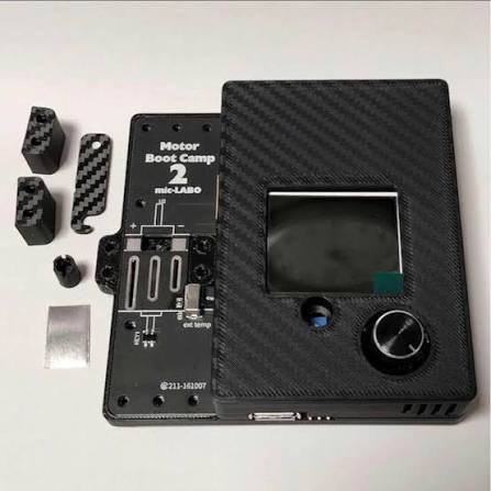
This project automates the break-in process for small brushed motors by running them through a controlled sequence of power levels over time. The system uses an ESP32 to drive a 3V Mini 4WD motor via a DRV8833 motor driver, monitoring RPM with an optical tachometer module while enforcing safety through a latching emergency stop switch. The guide provides a complete wiring diagram, parts list, and step-by-step assembly instructions covering motor power conditioning, noise suppression, sensor integration, and safety circuit setup.
The included firmware enables web-based control of multi-stage break-in programs, logging RPM and power data throughout the run for analysis. Builders will learn how to configure custom break-in sequences, read real-time motor telemetry, and safely operate the system with hardware-level emergency shutdown protection.
Wiring diagram
Gather all the parts
Assemble it in 5 steps
1. Prepare safe motor power
With all power disconnected, set the bench supply to 3.0 V and a 0.5 A current limit. Connect positive to driver VM and negative to driver GND and ESP32 GND. Power the ESP32 separately by USB. Leave driver B outputs disconnected.
- Never connect motor power to the ESP32 3V3 pin. This design is only for small 3 V motors within the current limit; high-current racing motors need a larger driver.
2. Wire motor and noise suppression
Connect driver AOUT1 and AOUT2 to the motor terminals. Put the ceramic capacitor directly across those terminals. Put the electrolytic capacitor across VM and GND near the driver, with its striped negative lead to GND. Connect AIN1 to GPIO25 for speed control; tie AIN2 and both B inputs to GND.
- Reversing the electrolytic capacitor can make it burst. Secure the motor in a clamp and guard the rotating shaft; do not use an unbalanced paper disk.
3. Add the hardware stop
Connect GPIO26 through the stop switch COM and normally closed NC contacts to driver nSLEEP. Connect the 10 kohm resistor from nSLEEP to GND and GPIO33 to nSLEEP for stop sensing. Connect nFAULT to GPIO32. Pressing the latching switch opens the enable circuit even without Wi-Fi. Release it before starting a new run.
- Verify the stop really disables the driver before attaching the motor. Cut motor supply power before touching the shaft.
4. Set up RPM sensing
Power the optical module from 3V3, not 5V. Connect GND to GND and DO to GPIO27 for rotation pulses. Leave AO disconnected. Aim the sensor at one reflective mark on a balanced dark shaft collar, starting about 2 mm away. Adjust its knob so the output changes once per revolution while turning the shaft by hand with motor power off.
- Use exactly one mark per revolution. Poor contrast or multiple marks gives incorrect RPM. The sensor module contains its own IR LED resistor.
5. Check before a run
Confirm polarity and shared ground before enabling supply output. Start with the default short low-power steps and stay beside the motor. Stop if it gets hot, vibrates, smells, or the supply reaches its current limit. This is a dry break-in setup; do not run the motor in liquid.
- PWM controls average drive
- not an exact motor voltage or regulated RPM. The program saves in flash; CSV logs are lost on reset or the next run. No temperature or current is measured.
Review all connections
1. Connections between "supply" and "ESP32"
2. Connections between "driver" and "ESP32"
3. Connections between "stop" and "ESP32"
4. Connections between "pulldown" and "ESP32"
5. Connections between "rpm" and "ESP32"
6. Connections between "bulk" and "ESP32"
7. Connections between "noise" and "ESP32"
Deploy the firmware
#include <Arduino.h>
#include <WiFi.h>
#include <WebServer.h>
#include <Preferences.h>
#include <esp_arduino_version.h>
WebServer web(80);
Preferences prefs;
constexpr int PWM=25, ENABLE=26, SENSE=33, FAULT=32, TACH=27;
volatile uint32_t pulses=0,lastEdge=0;
portMUX_TYPE mux=portMUX_INITIALIZER_UNLOCKED;
void IRAM_ATTR tick(){uint32_t t=micros(); if(t-lastEdge<100)return; lastEdge=t; portENTER_CRITICAL_ISR(&mux); pulses++; portEXIT_CRITICAL_ISR(&mux);}
struct Step{uint16_t seconds; uint8_t power;};
Step steps[12]; int count=0,idx=0,duty=0;
struct Sample{uint32_t ms; float rpm; uint8_t step,power;};
Sample samples[1801]; int used=0;
bool running=false; uint32_t began=0,stepAt=0,sampleAt=0; float rpmValue=0;
String reason="Idle",program="60,25\n60,40\n60,55";
void drive(int percent){duty=percent;
#if ESP_ARDUINO_VERSION_MAJOR >= 3
ledcWrite(PWM,percent*255/100);
#else
ledcWrite(0,percent*255/100);
#endif
}
void halt(String why){drive(0);digitalWrite(ENABLE,LOW);running=false;reason=why;}
bool parse(String s){int n=0,total=0,pos=0; Step temp[12]; while(pos<(int)s.length()){int e=s.indexOf('\n',pos);if(e<0)e=s.length();String l=s.substring(pos,e);l.trim();pos=e+1;if(!l.length())continue;int sec,power;char extra;if(sscanf(l.c_str(),"%d,%d %c",&sec,&power,&extra)!=2||sec<1||sec>1800||power<0||power>100||n>=12)return false;total+=sec;if(total>1800)return false;temp[n++]={(uint16_t)sec,(uint8_t)power};}if(!n)return false;memcpy(steps,temp,n*sizeof(Step));count=n;return true;}
const char page[] PROGMEM=R"HTML(<!doctype html><meta name="viewport" content="width=device-width"><title>Motor break-in</title><h1>Motor break-in</h1><p>Secure motor and guard shaft. Never leave running unattended.</p><p id="state"></p><p>Program: seconds,power percent, one step per line. Up to 12 steps / 30 minutes. Power is PWM duty, NOT regulated RPM or voltage.</p><textarea id="p" rows="12" cols="28"></textarea><p><button onclick="send('/save')">Save program</button> <button onclick="send('/start')">Start new log</button> <button onclick="fetch('/stop',{method:'POST'})">STOP</button></p><a href="/log.csv">Download CSV</a><p>Logs are held in memory. Download before starting again or removing power. Physical stop switch works without Wi-Fi.</p><script>fetch('/program').then(r=>r.text()).then(t=>p.value=t);function send(url){fetch(url,{method:'POST',body:new URLSearchParams({p:p.value})}).then(r=>r.text()).then(alert)}setInterval(()=>fetch('/status').then(r=>r.text()).then(t=>document.getElementById('state').textContent=t),1000)</script>)HTML";
void setup(){
 pinMode(ENABLE,OUTPUT);digitalWrite(ENABLE,LOW);pinMode(SENSE,INPUT);pinMode(FAULT,INPUT_PULLUP);pinMode(TACH,INPUT_PULLUP);
#if ESP_ARDUINO_VERSION_MAJOR >= 3
 ledcAttach(PWM,20000,8);
#else
 ledcSetup(0,20000,8);ledcAttachPin(PWM,0);
#endif
 drive(0);attachInterrupt(digitalPinToInterrupt(TACH),tick,FALLING);Serial.begin(115200);
 prefs.begin("breakin",false);program=prefs.getString("program",program);if(!parse(program)){program="60,25\n60,40\n60,55";parse(program);}
 WiFi.mode(WIFI_AP);WiFi.softAP("Motor-Break-In","MotorRun123");
 web.on("/",[]{web.send_P(200,"text/html",page);});web.on("/program",[]{web.send(200,"text/plain",program);});
 web.on("/status",[]{web.send(200,"text/plain",reason+" | RPM: "+String(rpmValue,0)+" | Power: "+String(duty)+"% | Samples: "+String(used));});
 web.on("/save",HTTP_POST,[]{if(running){web.send(409,"text/plain","Stop first");return;}if(!parse(web.arg("p"))){web.send(400,"text/plain","Invalid program: seconds 1-1800, power 0-100; max 12 steps and 1800 seconds total");return;}program=web.arg("p");prefs.putString("program",program);web.send(200,"text/plain","Saved");});
 web.on("/start",HTTP_POST,[]{if(running){web.send(409,"text/plain","Already running");return;}if(!parse(web.arg("p"))){web.send(400,"text/plain","Invalid program");return;}drive(0);digitalWrite(ENABLE,HIGH);delay(2);if(!digitalRead(SENSE)||!digitalRead(FAULT)){halt("Stop switch or driver fault");web.send(409,"text/plain",reason);return;}used=0;idx=0;rpmValue=0;portENTER_CRITICAL(&mux);pulses=0;portEXIT_CRITICAL(&mux);began=stepAt=sampleAt=millis();running=true;reason="Running";drive(steps[0].power);web.send(200,"text/plain","Started; previous log cleared");});
 web.on("/stop",HTTP_POST,[]{halt("Stopped");web.send(200,"text/plain",reason);});
 web.on("/log.csv",[]{if(running){web.send(409,"text/plain","Stop before downloading");return;}web.sendHeader("Content-Disposition","attachment; filename=breakin.csv");web.setContentLength(CONTENT_LENGTH_UNKNOWN);web.send(200,"text/csv","");web.sendContent("elapsed_ms,step,pwm_percent,rpm\n");String b;for(int i=0;i<used;i++){auto &s=samples[i];b+=String(s.ms)+","+String(s.step)+","+String(s.power)+","+String(s.rpm,1)+"\n";if(b.length()>1000){web.sendContent(b);b="";}}web.sendContent(b);web.sendContent("");});
 web.begin();Serial.println("Connect to Motor-Break-In, password MotorRun123; open http://192.168.4.1");
}
void loop(){
 uint32_t now=millis();
 if(running){
 if(!digitalRead(SENSE)||!digitalRead(FAULT))halt("Stop switch or driver fault - manual restart required");
 if(running&&now-sampleAt>=1000){uint32_t n;portENTER_CRITICAL(&mux);n=pulses;pulses=0;portEXIT_CRITICAL(&mux);rpmValue=n*60000.0f/(now-sampleAt);sampleAt=now;if(used<1801)samples[used++]={now-began,rpmValue,(uint8_t)(idx+1),(uint8_t)duty};if(duty>0&&now-stepAt>=5000&&rpmValue<60)halt("No RPM detected - check motor and optical sensor");}
 if(running&&now-stepAt>=steps[idx].seconds*1000UL){idx++;if(idx>=count)halt("Complete");else{stepAt=now;drive(steps[idx].power);}}
 }
 web.handleClient();delay(1);
}

// Verified wiring: PWM25, enable26, enable sense33, fault32, tach27.
Remix this project
Make it yours in one click
Open a full copy of this project in your own Schematik workspace, diagram, code, parts, and assembly steps included. Swap the sensor, add features, or redesign the whole thing with AI. The author's original stays untouched.