Community project
Automated Greenhouse Control
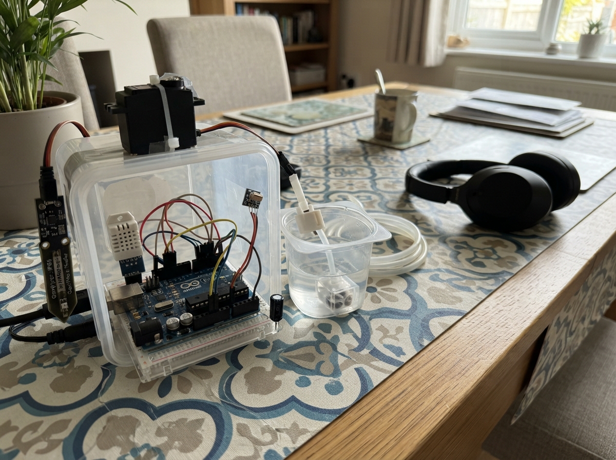
This automated greenhouse control system uses an ESP32 microcontroller to monitor and regulate temperature, humidity, soil moisture, light levels, and water availability. The system reads data from a DHT22 temperature/humidity sensor, capacitive soil moisture probe, light sensor, rain detector, and float switch to make real-time decisions about watering, heating, cooling, and lighting.
This guide provides a complete wiring diagram, parts list, and step-by-step assembly instructions to build a fully functional greenhouse automation system. The included firmware handles sensor calibration, relay control for the grow lamp and water pump, servo-driven roof ventilation, and a local web interface for monitoring. Assembly follows a logical sequence starting with sensor connections and ending with high-voltage load wiring for safe operation.
Wiring diagram
Gather all the parts
Assemble it in 6 steps
1. Deja todo apagado al comenzar
Coloca el ESP32, las fuentes, los relés y la pantalla en una zona seca. No conectes todavía el USB ni las fuentes de 5 V y 12 V; así ninguna carga se enciende mientras haces las conexiones.
- Etiqueta los cables de 3V3, 5V, 12V y GND antes de cerrar la caja.
- No unas el positivo de 12 V con los pines de 3.3 V o 5 V del ESP32: puede dañar la placa.
2. Conecta los sensores y la boya
Conecta DHT22: VCC → 3V3 (alimentación), GND → GND (tierra), DATA → GPIO4 (señal). Sensor de suelo: VCC → 3V3 (alimentación), GND → GND (tierra), AOUT → GPIO36 (señal). Módulo de luz: VCC → 3V3 (alimentación), GND → GND (tierra), AO → GPIO32 (señal). Módulo de lluvia: VCC → 3V3 (alimentación), GND → GND (tierra), DO → GPIO33 (señal). Boya: un cable → GND (tierra), el otro → GPIO23 (señal).
- Monta la LDR donde reciba luz del cultivo, pero sin recibir directamente la luz de la lámpara.
- El módulo de lluvia debe ir inclinado para que el agua pueda escurrir.
- Todos estos sensores van a 3.3 V; conectarlos a 5 V puede hacer que sus señales dañen el ESP32.
3. Cablea la pantalla LCD
Conecta VCC de lcd_display → +5V (alimentación) y GND → GND (tierra). En lcd_level_shifter conecta LV → 3V3 (lado ESP32), HV → +5V (lado pantalla) y GND → GND (tierra). Conecta LV1 → GPIO21 (datos SDA), LV2 → GPIO22 (reloj SCL), HV1 → SDA de lcd_display (datos) y HV2 → SCL de lcd_display (reloj).
- La pantalla suele tener un pequeño tornillo azul de contraste: gíralo despacio si la luz de fondo enciende pero no aparecen letras.
- No conectes SDA o SCL de una pantalla alimentada a 5 V directamente al ESP32: el conversor protege sus pines de 3.3 V.
4. Cablea las cargas de 5 V
Desde supply_5v conecta +5V al cable rojo del servo, VCC de los tres relés y al terminal positivo del condensador. Conecta GND de supply_5v a GND del ESP32, cable marrón del servo, GND de los tres relés, terminal negativo del condensador y cable negro de la bomba. Conecta el cable naranja del servo → GPIO13 (señal), IN de pump_relay → GPIO25 (señal), IN de lamp_relay → GPIO26 (señal) e IN de fan_relay → GPIO27 (señal). Conecta +5V → COM de pump_relay y NO de pump_relay → cable rojo de la bomba (potencia).
- La pata del condensador marcada con una franja menos va a GND; la otra pata va a +5 V.
- Usa cables cortos y suficientemente gruesos para los cables rojo y marrón del servo.
- No alimentes el servo, bomba o relés desde el pin 5V del ESP32: un pico de corriente puede reiniciar o dañar la placa.
5. Conecta la lámpara y el cooler de 12 V
Con supply_12v desenchufada, conecta +12V → COM de lamp_relay (potencia). Haz un puente desde ese COM hasta COM de fan_relay (distribuye los 12 V). Conecta NO de lamp_relay → LAMP+ de grow_lamp (potencia), LAMP- de grow_lamp → GND de supply_12v (retorno). Conecta NO de fan_relay → FAN+ de vent_fan (potencia) y FAN- de vent_fan → GND de supply_12v (retorno).
- Usa borneras cerradas y cables adecuados para la corriente indicada en la lámpara.
- La fuente de 12 V debe ser regulada y capaz de entregar al menos 10 A.
- No conectes nunca la lámpara, el cooler ni los contactos COM y NO directamente a la red eléctrica doméstica.
- No toques los bornes de 12 V con la fuente conectada.
6. Revisa el montaje
Comprueba que ningún cable de +12 V llega al ESP32. El cooler y la lámpara tienen relés separados, por lo que el programa puede encender uno sin encender el otro. La LCD debe encender su luz de fondo al encender la fuente de 5 V. GPIO16 y GPIO17 quedan libres para instalar después el MH-Z19B.
- Antes de usar riego real, prueba la boya y la bomba en un recipiente; la bomba debe detenerse cuando el nivel está bajo.
- Mantén el ESP32, los relés y ambas fuentes alejados de salpicaduras.
- Desconecta las dos fuentes antes de mover o modificar cables.
Review all connections
1. Connections between "dht22_air" and "ESP32"
2. Connections between "soil_sensor" and "ESP32"
3. Connections between "rain_sensor" and "ESP32"
4. Connections between "tank_float" and "ESP32"
5. Connections between "roof_servo" and "ESP32"
6. Connections between "servo_bulk_capacitor" and "ESP32"
7. Connections between "pump_relay" and "ESP32"
8. Connections between "supply_5v" and "ESP32"
9. Connections between "pump" and "ESP32"
10. Connections between "lamp_relay" and "ESP32"
11. Connections between "grow_lamp" and "ESP32"
12. Connections between "ldr_light" and "ESP32"
13. Connections between "lcd_display" and "ESP32"
14. Connections between "lcd_level_shifter" and "ESP32"
15. Connections between "fan_relay" and "ESP32"
16. Connections between "vent_fan" and "ESP32"
17. Connections between "supply_12v" and "ESP32"
Deploy the firmware
#include <Arduino.h>
#include <WiFi.h>
#include <WebServer.h>
#include <DHT.h>
#include <ESP32Servo.h>
#include <Wire.h>
#include <LiquidCrystal_I2C.h>

// GPIO16 and GPIO17 are intentionally left unused for a future MH-Z19B CO2 sensor.
constexpr int DHT_PIN = 4;
constexpr int SOIL_PIN = 36;
constexpr int LDR_PIN = 32;
constexpr int RAIN_PIN = 33;
constexpr int FLOAT_PIN = 23;
constexpr int LCD_SDA_PIN = 21;
constexpr int LCD_SCL_PIN = 22;
// GPIO27 drives the relay that switches the 12 V cooler; it does not power the cooler directly.
constexpr int FAN_PIN = 27;
constexpr int SERVO_PIN = 13;
constexpr int PUMP_RELAY_PIN = 25;
constexpr int LAMP_RELAY_PIN = 26;

constexpr uint8_t DHT_TYPE = DHT22;
constexpr bool RELAY_ON = HIGH;
constexpr bool RELAY_OFF = LOW;
constexpr bool RAIN_DETECTED_LEVEL = LOW;
constexpr bool TANK_LOW_WHEN_CLOSED = true;

// Calibrate these two readings after installing the soil probe.
constexpr int SOIL_DRY_RAW = 2600;
constexpr int SOIL_WET_RAW = 1300;
constexpr int SOIL_START_WATERING_PERCENT = 35;
constexpr int SOIL_STOP_WATERING_PERCENT = 55;
// These thresholds use the AO output of the 3.3 V photoresistor module.
constexpr int LIGHT_ON_RAW = 1500;
constexpr int LIGHT_OFF_RAW = 1900;
constexpr float FAN_ON_C = 29.0f;
constexpr float FAN_OFF_C = 27.0f;
constexpr float HEAT_ON_C = 18.0f;
constexpr float HEAT_OFF_C = 20.0f;
constexpr int ROOF_OPEN_ANGLE = 105;
constexpr int ROOF_CLOSED_ANGLE = 15;

const char *AP_NAME = "Invernadero-ESP32";
const char *AP_PASSWORD = "Greenhouse2026";

DHT dht(DHT_PIN, DHT_TYPE);
Servo roofServo;
LiquidCrystal_I2C lcd(0x27, 16, 2);
WebServer server(80);

bool automaticMode = true;
bool pumpOn = false;
bool fanOn = false;
bool lampOn = false;
bool roofOpen = false;
bool tankLow = true;
bool raining = false;
float temperatureC = NAN;
float humidityPct = NAN;
int soilRaw = 0;
int soilPercent = 0;
int lightRaw = 0;
unsigned long lastReadMs = 0;
String lastLcdLine1;
String lastLcdLine2;

String paddedLcdLine(const char *text) {
  String line(text);
  while (line.length() < 16) line += ' ';
  return line.substring(0, 16);
}

void updateLcd() {
  char temperatureLine[24];
  char humidityLine[24];
  if (isnan(temperatureC)) {
    snprintf(temperatureLine, sizeof(temperatureLine), "Temp: --.- C");
  } else {
    snprintf(temperatureLine, sizeof(temperatureLine), "Temp: %4.1f C", temperatureC);
  }
  if (isnan(humidityPct)) {
    snprintf(humidityLine, sizeof(humidityLine), "Humed: --.- %%");
  } else {
    snprintf(humidityLine, sizeof(humidityLine), "Humed: %4.1f %%", humidityPct);
  }

  String line1 = paddedLcdLine(temperatureLine);
  String line2 = paddedLcdLine(humidityLine);
  if (line1 != lastLcdLine1) {
    lcd.setCursor(0, 0);
    lcd.print(line1);
    lastLcdLine1 = line1;
  }
  if (line2 != lastLcdLine2) {
    lcd.setCursor(0, 1);
    lcd.print(line2);
    lastLcdLine2 = line2;
  }
}

void setPump(bool on) {
  pumpOn = on;
  digitalWrite(PUMP_RELAY_PIN, on ? RELAY_ON : RELAY_OFF);
}

void setLamp(bool on) {
  lampOn = on;
  digitalWrite(LAMP_RELAY_PIN, on ? RELAY_ON : RELAY_OFF);
}

void setFan(bool on) {
  fanOn = on;
  digitalWrite(FAN_PIN, on ? HIGH : LOW);
}

void setRoof(bool open) {
  roofOpen = open;
  roofServo.write(open ? ROOF_OPEN_ANGLE : ROOF_CLOSED_ANGLE);
}

int soilPercentFromRaw(int raw) {
  long percent = map(raw, SOIL_DRY_RAW, SOIL_WET_RAW, 0, 100);
  return constrain(percent, 0, 100);
}

bool isTankLow() {
  bool contactClosed = digitalRead(FLOAT_PIN) == LOW;
  return TANK_LOW_WHEN_CLOSED ? contactClosed : !contactClosed;
}

void readSensors() {
  temperatureC = dht.readTemperature();
  humidityPct = dht.readHumidity();
  soilRaw = analogRead(SOIL_PIN);
  soilPercent = soilPercentFromRaw(soilRaw);
  lightRaw = analogRead(LDR_PIN);
  raining = digitalRead(RAIN_PIN) == RAIN_DETECTED_LEVEL;
  tankLow = isTankLow();
}

void runAutomaticControl() {
  if (tankLow) {
    setPump(false);
  } else if (soilPercent <= SOIL_START_WATERING_PERCENT) {
    setPump(true);
  } else if (soilPercent >= SOIL_STOP_WATERING_PERCENT) {
    setPump(false);
  }

  if (!isnan(temperatureC)) {
    if (temperatureC >= FAN_ON_C) setFan(true);
    else if (temperatureC <= FAN_OFF_C) setFan(false);

    bool needsLamp = temperatureC <= HEAT_ON_C || lightRaw <= LIGHT_ON_RAW;
    bool canTurnLampOff = temperatureC >= HEAT_OFF_C && lightRaw >= LIGHT_OFF_RAW;
    if (needsLamp) setLamp(true);
    else if (canTurnLampOff) setLamp(false);

    setRoof(!raining && temperatureC >= FAN_ON_C);
  } else {
    setPump(false);
    setFan(false);
    setLamp(false);
    setRoof(false);
  }

  if (raining) setRoof(false);
}

String stateJson() {
  String json = "{";
  json += "\"automatic\":" + String(automaticMode ? "true" : "false");
  json += ",\"temperatureC\":" + String(temperatureC, 1);
  json += ",\"humidityPct\":" + String(humidityPct, 1);
  json += ",\"soilRaw\":" + String(soilRaw);
  json += ",\"soilPercent\":" + String(soilPercent);
  json += ",\"lightRaw\":" + String(lightRaw);
  json += ",\"raining\":" + String(raining ? "true" : "false");
  json += ",\"tankLow\":" + String(tankLow ? "true" : "false");
  json += ",\"pump\":" + String(pumpOn ? "true" : "false");
  json += ",\"fan\":" + String(fanOn ? "true" : "false");
  json += ",\"lamp\":" + String(lampOn ? "true" : "false");
  json += ",\"roofOpen\":" + String(roofOpen ? "true" : "false");
  json += "}";
  return json;
}

void sendHome() {
  const char page[] PROGMEM = R"HTML(
<!doctype html><html><head><meta name="viewport" content="width=device-width,initial-scale=1">
<style>body{font-family:Arial;margin:20px;background:#eef6ee;color:#173d1d}button{padding:10px;margin:4px;border-radius:8px;border:1px solid #497a50;background:white}pre{background:white;padding:12px;border-radius:8px;white-space:pre-wrap}</style></head>
<body><h1>Invernadero automatizado</h1><p>Conéctate a esta página desde el teléfono para ver el estado y elegir automático o manual.</p>
<button onclick="go('/auto?enabled=1')">Modo automático</button><button onclick="go('/auto?enabled=0')">Modo manual</button><br>
<button onclick="go('/control?pump=1')">Bomba ON</button><button onclick="go('/control?pump=0')">Bomba OFF</button>
<button onclick="go('/control?fan=1')">Ventilador ON</button><button onclick="go('/control?fan=0')">Ventilador OFF</button>
<button onclick="go('/control?lamp=1')">Lámpara ON</button><button onclick="go('/control?lamp=0')">Lámpara OFF</button>
<button onclick="go('/control?roof=open')">Abrir techo</button><button onclick="go('/control?roof=close')">Cerrar techo</button>
<pre id="s">Cargando...</pre><script>function go(u){fetch(u).then(load)}function load(){fetch('/state').then(r=>r.json()).then(x=>{document.getElementById('s').textContent=JSON.stringify(x,null,2)})}load();setInterval(load,2000);</script></body></html>
)HTML";
  server.send(200, "text/html; charset=utf-8", page);
}

void setupWebServer() {
  server.on("/", HTTP_GET, sendHome);
  server.on("/state", HTTP_GET, []() { server.send(200, "application/json", stateJson()); });
  server.on("/auto", HTTP_GET, []() {
    if (server.hasArg("enabled")) automaticMode = server.arg("enabled") == "1";
    server.send(200, "application/json", stateJson());
  });
  server.on("/control", HTTP_GET, []() {
    if (automaticMode) {
      server.send(409, "application/json", "{\"error\":\"Cambia primero a modo manual\"}");
      return;
    }
    if (server.hasArg("pump")) setPump(server.arg("pump") == "1" && !tankLow);
    if (server.hasArg("fan")) setFan(server.arg("fan") == "1");
    if (server.hasArg("lamp")) setLamp(server.arg("lamp") == "1");
    if (server.hasArg("roof")) setRoof(server.arg("roof") == "open" && !raining);
    server.send(200, "application/json", stateJson());
  });
  server.begin();
}

void setup() {
  Serial.begin(115200);
  pinMode(RAIN_PIN, INPUT);
  pinMode(FLOAT_PIN, INPUT_PULLUP);
  pinMode(FAN_PIN, OUTPUT);
  pinMode(PUMP_RELAY_PIN, OUTPUT);
  pinMode(LAMP_RELAY_PIN, OUTPUT);
  setPump(false);
  setFan(false);
  setLamp(false);
  dht.begin();
  analogReadResolution(12);
  roofServo.setPeriodHertz(50);
  roofServo.attach(SERVO_PIN, 500, 2500);
  setRoof(false);
  Wire.begin(LCD_SDA_PIN, LCD_SCL_PIN);
  lcd.init();
  lcd.backlight();
  lcd.setCursor(0, 0);
  lcd.print("Invernadero");
  lcd.setCursor(0, 1);
  lcd.print("Iniciando...");
  WiFi.mode(WIFI_AP);
  WiFi.softAP(AP_NAME, AP_PASSWORD);
  setupWebServer();
  Serial.print("Panel del invernadero: http://");
  Serial.println(WiFi.softAPIP());
}

void loop() {
  server.handleClient();
  unsigned long now = millis();
  if (now - lastReadMs >= 2000) {
    lastReadMs = now;
    readSensors();
    updateLcd();
    if (automaticMode) runAutomaticControl();
  }
  delay(10);
}
Remix this project
Make it yours in one click
Open a full copy of this project in your own Schematik workspace, diagram, code, parts, and assembly steps included. Swap the sensor, add features, or redesign the whole thing with AI. The author's original stays untouched.