Community project
Build A Working Bench-top Prototype Of Iot-enabl
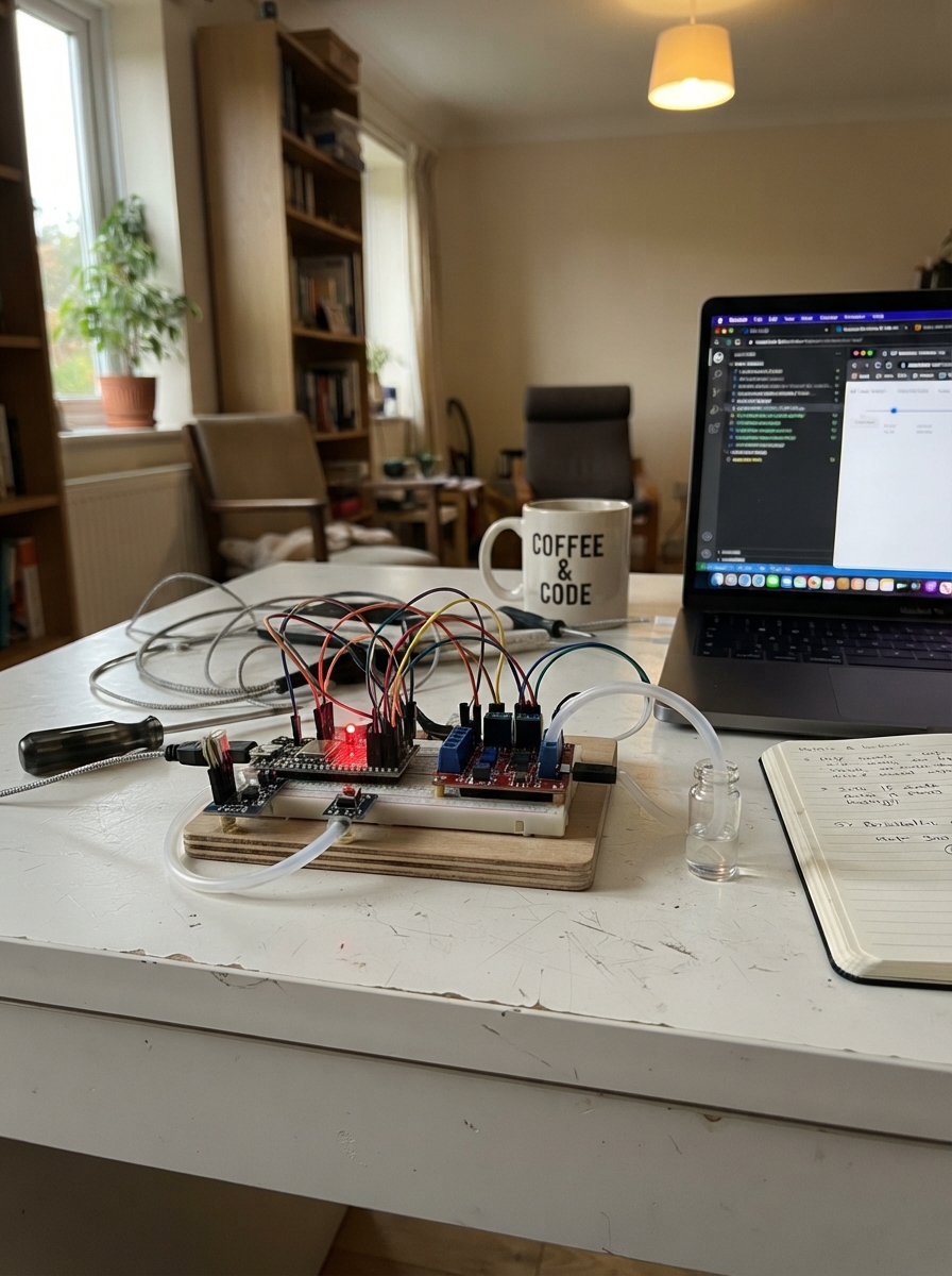
This guide builds a water-only bench prototype for testing IoT-enabled peristaltic pump control. The system combines an ESP32 microcontroller, TB6612FNG motor driver, 5 V peristaltic pump, IR drop sensor, pressure transducer, and safety alarm outputs to create a research rig capable of precise flow measurement and remote command execution over MQTT. Readers will receive a complete wiring diagram, parts list with pinout assignments, step-by-step assembly instructions, and pre-configured Arduino firmware with calibration and fault-detection routines.
The prototype emphasizes safety and reproducibility: a physical STOP button provides hard override, pressure and drop-rate monitoring detect occlusion and sensor faults, and a water-only design keeps the bench rig simple and non-hazardous. Assembly follows a logical sequence—power rails first, then motor driver and pump, sensor wiring, alarm outputs, and finally calibration steps before any controlled test runs.
Wiring diagram

Gather all the parts
Assemble it in 8 steps
1. Keep this as a water-only bench rig
Place the ESP32, driver board, sensor boards, and tubing on a dry breadboard area. Put the peristaltic pump beside the breadboard and route only water through clean silicone tubing into a measuring cup; never connect this prototype to a person or to medication.
- A peristaltic pump keeps the water inside the tube, away from the motor.
- Keep all electronics above the water container so spills run away from the board.
- This is an academic water-test prototype, not a certified infusion device; use it only on a supervised bench.
2. Make the shared power rails
Use the 5 V, 2 A USB supply for the red 5 V breadboard rail and its ground for the blue ground rail. Connect ESP32 VIN/5V to the 5 V rail and ESP32 GND to the ground rail; the ESP32 creates its own 3.3 V rail. Connect every ground listed below to this same ground rail.
- Use short, thicker jumper wires for the 5 V and ground path between the supply, driver, and pump.
- The ESP32 USB port may be used for programming, but do not rely on it to power the pump.
- Do not power the pump from an ESP32 GPIO pin — the driver board and separate 5 V supply carry the motor current.
- Disconnect 5 V power before moving breadboard wires; a short can overheat wires or damage the ESP32.
3. Wire the motor driver and pump
Connect TB6612FNG VM to 5 V (motor power), VCC to ESP32 3V3 (logic power), and GND to the common ground (ground). Connect AIN1 to GPIO25 (direction), AIN2 to GPIO26 (direction), and PWMA to GPIO27 (speed-control signal). Connect BIN1, BIN2, and PWMB to GND because motor channel B is unused. Connect driver A01 to pump MOTOR+ and A02 to pump MOTOR− (motor power). Put C1 across driver VCC and GND, and C2 across VM and GND with the capacitor’s + leg on VM.
- If water moves the wrong direction, swap the two pump motor wires only after removing power.
- Confirm the pump’s measured stall current is below the TB6612FNG module’s 1 A per-channel limit before powering it.
- C2 is polarized: its marked minus stripe must go to ground; reversed electrolytic capacitors can rupture.
- Most TB6612FNG modules already protect the motor internally; do not fit a 1N4007 across A01/A02 because it interferes with the H-bridge.
4. Add the physical STOP override
Connect one STOP button leg to GND (ground). Connect its other leg, SIGNAL, both to GPIO33 (stop signal) and to the driver STBY pin (hardware enable). Connect R2, the 10 kΩ resistor, from SIGNAL to 3V3 (pull-up). Pressing the button pulls STBY low, which directly disables the motor driver, while GPIO33 tells the firmware to latch the fault.
- Before testing water flow, power the board and hold STOP down: the pump must remain still even if a START command is sent.
- Use a normally-open push button; the two legs used must be on opposite switch sides, not two legs already joined internally.
- This hardware STOP is an emergency stop for the driver enable line, but it is not a safety-certified emergency-stop system.
5. Wire the drop sensor
Power the 3.3 V open-collector IR drop sensor from ESP32 3V3 (power) and common GND (ground). Connect sensor OUT to GPIO32 (drop signal). Connect R1, the 10 kΩ resistor, from OUT to 3V3 (pull-up), then mount the beam so each water drop crosses it once.
- Use the sensor’s 3.3 V version only; its OUT line must never be pulled up to 5 V because ESP32 inputs are 3.3 V only.
- Start with a slow drip and watch the Serial reading for drops/s before closing the control loop.
- A wet sensor or a beam aimed through a stream instead of individual drops can create false counts and unsafe pump behavior.
6. Wire the pressure sensor safely
Connect the 0–100 kPa sensor VCC to 5 V (power) and GND to common ground (ground). Put C3, the 0.1 µF capacitor, directly between its VCC and GND pins. Make a divider: connect sensor VOUT to R4 20 kΩ, connect R4’s other end to GPIO34, and connect R5 39 kΩ from GPIO34 to GND. This reduces the sensor’s 4.5 V maximum output to about 3.0 V for the ESP32 input.
- Keep the pressure connection downstream of the pump and use water-compatible fittings.
- Check with a meter that GPIO34 never exceeds 3.3 V before plugging it into the ESP32.
- Connecting a 5 V analog sensor output directly to GPIO34 can permanently damage the ESP32.
7. Wire the alarm light and buzzer
Connect GPIO22 to R3 220 Ω, then R3 to the red LED long leg (anode); connect the LED short leg to GND (alarm light). Connect GPIO23 to R6 1 kΩ, then R6 to the NPN transistor base. Connect transistor emitter to GND and collector to buzzer GND; connect buzzer VCC to 5 V. Connect D1 across the buzzer with its striped end to 5 V and its unstriped end to the transistor collector.
- Check the transistor’s printed pin order; 2N2222 and BC547 packages may have different lead order.
- The active buzzer sounds when GPIO23 turns the transistor on.
- Swapping LED polarity prevents the alarm light from working; the long LED leg is the positive side.
- A transistor wired with the wrong lead order can heat up or fail.
8. Run the water calibration before controlled tests
Fill the tubing with water, place the outlet over a marked measuring container, and keep the STOP button within reach. After deployment, use the Serial command CAL 60, collect water for a timed run, then send CAL_RESULT followed by the measured millilitres. Repeat for PWM 100, 140, and 180, recording PWM, drops/s, and mL/min; the last measured drops-per-mL value is stored in the ESP32.
- Use the same tubing, fluid, height, and drop chamber position for calibration and tests.
- Begin later tests with SET_FLOW 1.0 and START; never exceed the firmware’s 5 mL/min local clamp.
- Do not start a run until the pressure reading is plausible, the drop sensor counts test drops, and the physical STOP has been checked.
Review all connections
1. Connections between "power_supply" and "ESP32"
2. Connections between "driver" and "ESP32"
3. Connections between "ir_drop_sensor" and "ESP32"
4. Connections between "pressure_sensor" and "ESP32"
5. Connections between "stop_button" and "ESP32"
6. Connections between "buzzer" and "ESP32"
7. Connections between "alarm_led" and "ESP32"
8. Connections between "r1_ir_pullup" and "ESP32"
9. Connections between "r2_stop_pullup" and "ESP32"
10. Connections between "r3_led" and "ESP32"
11. Connections between "q1_buzzer" and "ESP32"
12. Connections between "r5_pressure_bottom" and "ESP32"
13. Connections between "r6_buzzer_base" and "ESP32"
14. Connections between "c1_logic" and "ESP32"
15. Connections between "c2_motor" and "ESP32"
16. Connections between "c3_pressure" and "ESP32"
17. Connections between "r4_pressure_top" and "ESP32"
18. Connections between "d1_buzzer" and "ESP32"
Deploy the firmware
/*
  SMART MICRO-PUMP — WATER-ONLY BENCH RESEARCH PROTOTYPE (wiring verified)
  Not a medical device. Never connect to a person or use for IV delivery.
  Commands on Serial (newline terminated):
    SET_FLOW 2.0 | START | PAUSE | STOP | ACK_ALARM | RESUME
    CAL 140 | CAL_RESULT 10.0 | CAL_STOP | STATUS
*/
#include <Arduino.h>
#include <WiFi.h>
#include <WiFiClientSecure.h>
#include <PubSubClient.h>
#include <Preferences.h>
#include <esp_task_wdt.h>


struct CalibrationPoint { uint8_t pwm; float dropsPerSecond; float mlPerMin; };

enum PumpState { IDLE, CALIBRATING, RUNNING, PAUSED, COMPLETE, OCCLUSION_ALARM, FAULT };

enum FaultReason { NO_FAULT, STOP_PRESSED, OCCLUSION, NO_FLOW, PRESSURE_SENSOR_FAULT, IR_SENSOR_FAULT, NETWORK_TIMEOUT };


// Forward declarations
void IRAM_ATTR onDrop();
void writePumpPwm(uint8_t duty);
void pumpOff();
void alarmOutputs(bool active);
void latchFault(FaultReason why);
bool physicalStopPressed();
float readPressureKpa(bool &valid);
bool conditionsSafe();
void beginRun();
void pausePump();
void controlAndSafety();
void publishTelemetry();
void handleCommand(String command, bool remote);
void mqttCallback(char *topic, byte *payload, unsigned int length);
void serviceNetwork();

constexpr int AIN1_PIN = 25;
constexpr int AIN2_PIN = 26;
constexpr int PUMP_PWM_PIN = 27;
constexpr int DROP_PIN = 32;
constexpr int STOP_PIN = 33;
constexpr int PRESSURE_PIN = 34;
constexpr int ALARM_LED_PIN = 22;
constexpr int BUZZER_PIN = 23;

// ---- Experiment-specific constants: calibrate these with water before use ----
constexpr float KP = 28.0f;                 // PWM counts per (mL/min) error
constexpr float KI = 4.0f;                  // PWM counts per (mL/min*s) error
constexpr float KD = 2.0f;                  // PWM counts per (mL/min)/s error
constexpr uint8_t MIN_PWM = 55;             // experimentally find the pump's reliable start value
constexpr uint8_t MAX_PWM = 180;            // local hardware rate clamp; never exceed without revalidation
constexpr float LOCAL_MAX_FLOW_ML_MIN = 5.0f;
constexpr float DEFAULT_DROPS_PER_ML = 20.0f; // REPLACE using CAL_RESULT measurement
constexpr float DEFAULT_TARGET_FLOW_ML_MIN = 2.0f;
constexpr uint32_t SENSOR_TIMEOUT_MS = 12000;
constexpr float OCCLUSION_PRESSURE_KPA = 60.0f;
constexpr uint32_t CONTROL_PERIOD_MS = 250;
constexpr uint32_t DROP_DEBOUNCE_US = 2500;
constexpr uint32_t NETWORK_COMMAND_TIMEOUT_MS = 30000;
constexpr uint32_t STARTUP_NO_FLOW_GRACE_MS = 4000;
constexpr uint32_t WDT_TIMEOUT_S = 4;
constexpr uint32_t PWM_FREQ_HZ = 18000;
constexpr uint8_t PWM_BITS = 8;
constexpr uint8_t PUMP_PWM_CHANNEL = 1;

// Calibration table is a worksheet starter, not a pump model. Populate during water tests.

CalibrationPoint calibrationTable[] = {
  {60, 0.0f, 0.0f}, {100, 0.0f, 0.0f}, {140, 0.0f, 0.0f}, {180, 0.0f, 0.0f}
};
constexpr size_t CAL_POINTS = sizeof(calibrationTable) / sizeof(calibrationTable[0]);


volatile uint32_t totalDrops = 0;
volatile uint32_t windowDrops = 0;
volatile uint32_t lastDropUs = 0;
volatile uint32_t lastDropMs = 0;
PumpState state = IDLE;
FaultReason fault = NO_FAULT;
Preferences preferences;

float targetFlowMlMin = DEFAULT_TARGET_FLOW_ML_MIN;
float dropsPerMl = DEFAULT_DROPS_PER_ML;
float measuredDropsSec = 0.0f, measuredFlowMlMin = 0.0f;
float pressureKpa = 0.0f;
float integral = 0.0f, priorError = 0.0f;
uint8_t pwmDuty = 0;
uint32_t lastControlMs = 0, runStartedMs = 0;
uint32_t calibrationStartDrops = 0, calibrationStartMs = 0;
uint8_t calibrationPwm = 0;
bool remoteSessionActive = false;
uint32_t lastRemoteCommandMs = 0;

// Leave these empty for standalone local bench tests. With real broker credentials,
// this module uses TLS on 8883 and publishes the documented topic layout.
const char *DEVICE_ID = "bench-pump-01";
const char *WIFI_SSID = "";
const char *WIFI_PASSWORD = "";
const char *MQTT_HOST = "";
const uint16_t MQTT_TLS_PORT = 8883;
WiFiClientSecure tlsClient;
PubSubClient mqtt(tlsClient);

const char *stateName(PumpState s) {
  switch (s) { case IDLE:return "IDLE"; case CALIBRATING:return "CALIBRATING"; case RUNNING:return "RUNNING"; case PAUSED:return "PAUSED"; case COMPLETE:return "COMPLETE"; case OCCLUSION_ALARM:return "OCCLUSION_ALARM"; default:return "FAULT"; }
}
const char *faultName(FaultReason f) {
  switch (f) { case NO_FAULT:return "NONE"; case STOP_PRESSED:return "PHYSICAL_STOP"; case OCCLUSION:return "OCCLUSION"; case NO_FLOW:return "NO_FLOW_OR_AIR"; case PRESSURE_SENSOR_FAULT:return "PRESSURE_SENSOR"; case IR_SENSOR_FAULT:return "IR_SENSOR"; default:return "NETWORK_TIMEOUT"; }
}

void IRAM_ATTR onDrop() {
  uint32_t now = micros();
  if ((uint32_t)(now - lastDropUs) >= DROP_DEBOUNCE_US) {
    totalDrops++; windowDrops++; lastDropUs = now; lastDropMs = millis();
  }
}

void writePumpPwm(uint8_t duty) {
  ledcWrite(PUMP_PWM_CHANNEL, duty);
}
void pumpOff() {
  writePumpPwm(0); pwmDuty = 0;
  digitalWrite(AIN1_PIN, LOW); digitalWrite(AIN2_PIN, LOW);
}
void alarmOutputs(bool active) {
  digitalWrite(ALARM_LED_PIN, active ? HIGH : LOW);
  digitalWrite(BUZZER_PIN, active ? HIGH : LOW);
}
void latchFault(FaultReason why) {
  pumpOff(); fault = why;
  state = (why == OCCLUSION) ? OCCLUSION_ALARM : FAULT;
  alarmOutputs(true);
  Serial.printf("ALARM,%s\n", faultName(why));
}
bool physicalStopPressed() { return digitalRead(STOP_PIN) == LOW; }

float readPressureKpa(bool &valid) {
  uint32_t sum = 0;
  for (int i = 0; i < 8; ++i) { sum += analogRead(PRESSURE_PIN); delayMicroseconds(150); }
  float adcV = (sum / 8.0f) * 3.3f / 4095.0f;
  // 20k top / 39k bottom divider: sensor voltage = ADC voltage * 59/39.
  float sensorV = adcV * (59.0f / 39.0f);
  valid = sensorV >= 0.20f && sensorV <= 4.95f;
  return constrain((sensorV - 0.5f) * 25.0f, 0.0f, 100.0f); // sensor's stated 0.5–4.5 V transfer
}

bool conditionsSafe() {
  bool pressureValid = false;
  float p = readPressureKpa(pressureValid);
  return !physicalStopPressed() && pressureValid && p < OCCLUSION_PRESSURE_KPA;
}
void beginRun() {
  if (!conditionsSafe()) { latchFault(physicalStopPressed() ? STOP_PRESSED : PRESSURE_SENSOR_FAULT); return; }
  integral = 0; priorError = 0; runStartedMs = millis();
  noInterrupts(); windowDrops = 0; interrupts();
  state = RUNNING; fault = NO_FAULT; alarmOutputs(false);
  pwmDuty = MIN_PWM; digitalWrite(AIN1_PIN, HIGH); digitalWrite(AIN2_PIN, LOW); writePumpPwm(pwmDuty);
}
void pausePump() { pumpOff(); if (state == RUNNING || state == CALIBRATING) state = PAUSED; }

void controlAndSafety() {
  if (physicalStopPressed()) { if (state != FAULT || fault != STOP_PRESSED) latchFault(STOP_PRESSED); return; }
  bool pressureValid = false;
  pressureKpa = readPressureKpa(pressureValid);
  if (!pressureValid) { if (state == RUNNING || state == CALIBRATING) latchFault(PRESSURE_SENSOR_FAULT); return; }
  if (pressureKpa >= OCCLUSION_PRESSURE_KPA && (state == RUNNING || state == CALIBRATING)) { latchFault(OCCLUSION); return; }
  if (state != RUNNING) return;
  uint32_t now = millis();
  if (remoteSessionActive && (!mqtt.connected() || now - lastRemoteCommandMs > NETWORK_COMMAND_TIMEOUT_MS)) { latchFault(NETWORK_TIMEOUT); return; }
  if (pwmDuty >= MIN_PWM && now - runStartedMs > STARTUP_NO_FLOW_GRACE_MS && now - lastDropMs > SENSOR_TIMEOUT_MS) { latchFault(NO_FLOW); return; }
  if (now - lastControlMs < CONTROL_PERIOD_MS) return;
  float dt = (now - lastControlMs) / 1000.0f; lastControlMs = now;
  noInterrupts(); uint32_t drops = windowDrops; windowDrops = 0; interrupts();
  measuredDropsSec = drops / dt;
  measuredFlowMlMin = measuredDropsSec * 60.0f / dropsPerMl;
  float error = targetFlowMlMin - measuredFlowMlMin;
  float candidateIntegral = constrain(integral + error * dt, -20.0f, 20.0f);
  float derivative = (error - priorError) / dt;
  float output = KP * error + KI * candidateIntegral + KD * derivative;
  float requested = pwmDuty + output;
  uint8_t constrained = (uint8_t)constrain(requested, (float)MIN_PWM, (float)MAX_PWM);
  // Only retain the integral when saturation is not forcing the output farther outward.
  if ((requested == constrained) || (requested > MAX_PWM && error < 0) || (requested < MIN_PWM && error > 0)) integral = candidateIntegral;
  priorError = error; pwmDuty = constrained; writePumpPwm(pwmDuty);
}

void publishTelemetry() {
  if (!mqtt.connected()) return;
  char topic[80], payload[220];
  snprintf(topic, sizeof(topic), "smartpump/%s/telemetry", DEVICE_ID);
  snprintf(payload, sizeof(payload), "{\"state\":\"%s\",\"fault\":\"%s\",\"target_ml_min\":%.3f,\"flow_ml_min\":%.3f,\"drops_s\":%.3f,\"pressure_kpa\":%.2f,\"pwm\":%u}", stateName(state), faultName(fault), targetFlowMlMin, measuredFlowMlMin, measuredDropsSec, pressureKpa, pwmDuty);
  mqtt.publish(topic, payload, false);
}
void handleCommand(String command, bool remote) {
  command.trim(); command.toUpperCase();
  if (remote) { remoteSessionActive = true; lastRemoteCommandMs = millis(); }
  if (command.startsWith("SET_FLOW ")) {
    float requested = command.substring(9).toFloat();
    if (requested > 0.0f && requested <= LOCAL_MAX_FLOW_ML_MIN) targetFlowMlMin = requested;
    else Serial.println("REJECTED: flow exceeds local clamp or is invalid");
  } else if (command == "START") {
    if (state == IDLE || state == PAUSED) beginRun();
    else Serial.println("REJECTED: acknowledge faults, then explicitly RESUME");
  } else if (command == "PAUSE") pausePump();
  else if (command == "STOP") latchFault(STOP_PRESSED);
  else if (command == "ACK_ALARM") {
    if ((state == FAULT || state == OCCLUSION_ALARM) && conditionsSafe()) { fault = NO_FAULT; state = PAUSED; alarmOutputs(false); Serial.println("ACKNOWLEDGED: now use RESUME"); }
    else Serial.println("REJECTED: release STOP and remove pressure/sensor fault first");
  } else if (command == "RESUME") {
    if (state == PAUSED && fault == NO_FAULT && conditionsSafe()) beginRun();
    else Serial.println("REJECTED: safety conditions are not verified");
  } else if (command.startsWith("CAL ")) {
    if (state == IDLE || state == PAUSED) { calibrationPwm = constrain(command.substring(4).toInt(), MIN_PWM, MAX_PWM); calibrationStartDrops = totalDrops; calibrationStartMs = millis(); state = CALIBRATING; fault = NO_FAULT; alarmOutputs(false); digitalWrite(AIN1_PIN,HIGH); digitalWrite(AIN2_PIN,LOW); pwmDuty = calibrationPwm; writePumpPwm(pwmDuty); Serial.println("CAL running: collect water, then send CAL_RESULT <measured_mL>"); }
  } else if (command.startsWith("CAL_RESULT ")) {
    if (state == CALIBRATING) { float volume = command.substring(11).toFloat(); uint32_t d = totalDrops - calibrationStartDrops; float sec = (millis()-calibrationStartMs)/1000.0f; pumpOff(); state = PAUSED; if (volume > 0.0f && sec > 0.0f) { dropsPerMl = d / volume; preferences.putFloat("dropsMl", dropsPerMl); Serial.printf("CAL,%u,%.3f drops/s,%.3f mL/min,%.3f drops/mL SAVED\n", calibrationPwm, d/sec, volume*60.0f/sec, dropsPerMl); } }
  } else if (command == "CAL_STOP") pausePump();
  else if (command == "STATUS") { /* printed by periodic report */ }
  else Serial.println("Unknown command");
}
void mqttCallback(char *topic, byte *payload, unsigned int length) {
  String command; for (unsigned int i=0; i<length; ++i) command += (char)payload[i];
  handleCommand(command, true);
}
void serviceNetwork() {
  // Empty credentials deliberately leave the prototype in local bench mode.
  if (strlen(WIFI_SSID) == 0 || strlen(MQTT_HOST) == 0) return;
  if (WiFi.status() != WL_CONNECTED) return;
  if (!mqtt.connected()) {
    mqtt.setServer(MQTT_HOST, MQTT_TLS_PORT); mqtt.setCallback(mqttCallback);
    char clientId[48]; snprintf(clientId, sizeof(clientId), "%s-%08lx", DEVICE_ID, (unsigned long)ESP.getEfuseMac());
    if (mqtt.connect(clientId)) { char topic[80]; snprintf(topic,sizeof(topic),"smartpump/%s/command",DEVICE_ID); mqtt.subscribe(topic); }
  }
  mqtt.loop();
}
void setup() {
  Serial.begin(115200);
  pinMode(AIN1_PIN, OUTPUT); pinMode(AIN2_PIN, OUTPUT); pinMode(ALARM_LED_PIN, OUTPUT); pinMode(BUZZER_PIN, OUTPUT);
  pinMode(STOP_PIN, INPUT); pinMode(DROP_PIN, INPUT); // External 10 kΩ pull-ups are required.
  analogReadResolution(12); analogSetPinAttenuation(PRESSURE_PIN, ADC_11db);
  ledcSetup(PUMP_PWM_CHANNEL, PWM_FREQ_HZ, PWM_BITS); ledcAttachPin(PUMP_PWM_PIN, PUMP_PWM_CHANNEL);
  pumpOff(); alarmOutputs(false);
  attachInterrupt(digitalPinToInterrupt(DROP_PIN), onDrop, FALLING);
  preferences.begin("smartpump", false); dropsPerMl = preferences.getFloat("dropsMl", DEFAULT_DROPS_PER_ML);
#if ESP_ARDUINO_VERSION_MAJOR >= 3
  esp_task_wdt_config_t cfg = { .timeout_ms = WDT_TIMEOUT_S * 1000, .idle_core_mask = 0, .trigger_panic = true };
  esp_task_wdt_init(&cfg);
#else
  esp_task_wdt_init(WDT_TIMEOUT_S, true);
#endif
  esp_task_wdt_add(NULL);
  if (strlen(WIFI_SSID) > 0) WiFi.begin(WIFI_SSID, WIFI_PASSWORD);
  lastControlMs = millis(); lastDropMs = millis();
  Serial.println("Water-only smart pump ready. Pump defaults OFF. Send STATUS or SET_FLOW then START.");
}
void loop() {
  esp_task_wdt_reset();
  if (Serial.available()) handleCommand(Serial.readStringUntil('\n'), false);
  serviceNetwork(); controlAndSafety();
  static uint32_t lastReport = 0, lastPublish = 0;
  if (millis() - lastReport >= 1000) {
    lastReport = millis();
    float error = targetFlowMlMin - measuredFlowMlMin;
    Serial.printf("state=%s fault=%s wifi=%s target=%.3f flow=%.3f drops/s=%.3f pressure=%.2f pwm=%u error=%.3f\n", stateName(state), faultName(fault), WiFi.status()==WL_CONNECTED?"connected":"local/offline", targetFlowMlMin, measuredFlowMlMin, measuredDropsSec, pressureKpa, pwmDuty, error);
  }
  if (millis() - lastPublish >= 1000) { lastPublish = millis(); publishTelemetry(); }
}
Remix this project
Make it yours in one click
Open a full copy of this project in your own Schematik workspace — diagram, code, parts, and assembly steps included. Swap the sensor, add features, or redesign the whole thing with AI. The author's original stays untouched.