Community project
Depth Proximity Alert Logger
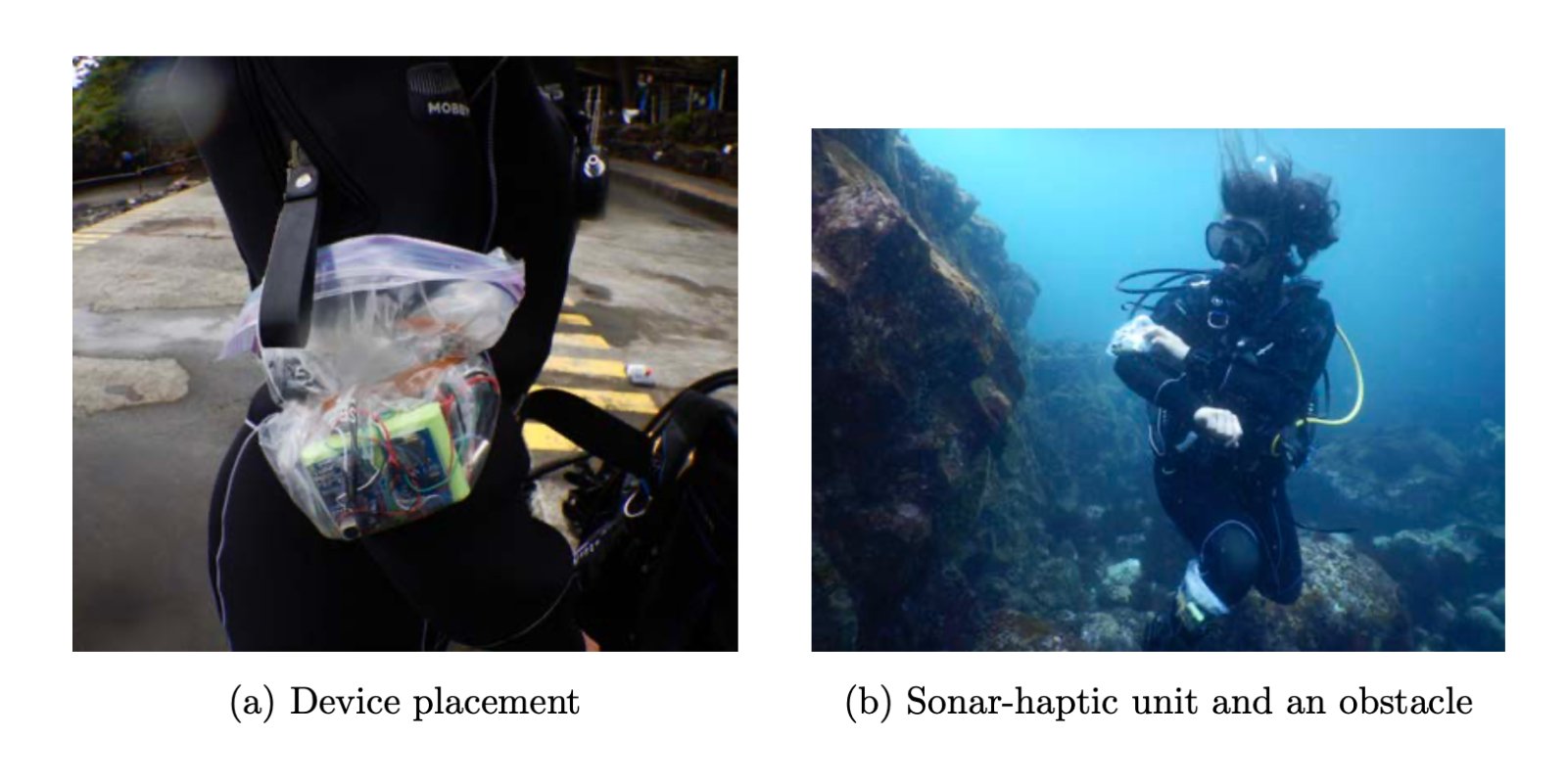
This project builds a wearable dive navigation system that combines waterproof sonar and depth sensing with haptic feedback to alert divers of obstacles and depth limits. The ESP32 monitors distance to nearby objects using the JSN-SR04T ultrasonic sensor and water pressure via the MS5837-30BA depth sensor, then triggers two independent haptic motors to communicate proximity and depth warnings through distinct vibration patterns—allowing divers to maintain situational awareness without looking at a screen.
The guide provides a complete parts list, wiring diagram showing the power distribution chain (9V battery stepped down to 5V and 3.3V), transistor driver circuits for both haptic actuators, and step-by-step assembly instructions. You'll also get the full ESP32 firmware that logs all sensor readings to a MicroSD card in CSV format while generating real-time haptic alerts based on configurable distance and depth thresholds.
Wiring diagram

Gather all the parts
Assemble it in 8 steps
1. Gather all components and tools
Collect everything before starting. You will need: ESP32-S3-DevKitC-1, JSN-SR04T ultrasonic sensor (driver board + cable), MS5837-30BA depth sensor, 2× ERM vibration motors, 2× 2N3904 NPN transistors, 2× 1N4001 diodes, 2× 10 Ω resistors, 2× 0.1 µF ceramic capacitors, MicroSD card module, MP1584 buck converter module, 9V rechargeable Li-Ion battery with connector, breadboard or PCB, hookup wire, soldering iron (if using PCB).
- Use a good quality 9V Li-Ion rechargeable such as the Nitecore PP9 or EBL 9V 600mAh — they maintain voltage far better than alkaline 9V batteries under load.
2. Set up the power chain (9V → 5V → 3.3V)
Connect the 9V battery positive terminal to the MP1584 buck converter VIN+ and battery negative to VIN−. Set the buck converter output to exactly 5.0V using its trim potentiometer and a multimeter BEFORE connecting the ESP32. Connect VOUT+ of the buck converter to the ESP32-S3 5V pin (VIN on the board header), and VOUT− to GND. The ESP32's onboard LDO then supplies clean 3.3V for sensors and actuators.
- The MP1584 module has a small blue trimpot. Turn clockwise to raise voltage, counter-clockwise to lower it. Measure with a multimeter before connecting.
- NEVER power the ESP32 from the 9V battery directly — it accepts 5V on its VIN pin, not 9V.
- Set and verify the buck converter output BEFORE connecting it to the ESP32.
3. Connect the JSN-SR04T sonar sensor
Plug the JSN-SR04T transducer cable into the driver board header. Connect the driver board: VCC → ESP32 3.3V rail, GND → ESP32 GND, TRIG → GPIO1, ECHO → GPIO2. The JSN-SR04T runs fine at 3.3V logic; no level-shifting required with the S3.
- The sealed transducer head can get wet — mount it facing forward on the diver's wrist unit or housing. The driver board itself must stay dry.
4. Connect the MS5837-30BA depth/pressure sensor
Connect the MS5837 sensor board: VDD → 3.3V, GND → GND, SDA → GPIO8, SCL → GPIO9. The Blue Robotics Bar30 module includes pull-up resistors on the breakout, so none are needed externally. If using a bare MS5837 chip, add 4.7 kΩ pull-ups from SDA and SCL to 3.3V.
- The Bar30 cable has a JST connector. If you are building for underwater use, the sensor is rated to 300m — house the electronics in a waterproof enclosure and route the sensor cable through a cable gland.
- The MS5837 is a 3.3V-only device. DO NOT connect VDD to 5V — it will be destroyed instantly.
5. Build ERM1 transistor drive circuit (Proximity motor)
Build the ERM1 (proximity alert) drive circuit: (a) Connect one end of the first 10 Ω resistor to GPIO3. (b) Connect the other end to the 2N3904 Q1 BASE pin. (c) Connect Q1 EMITTER to GND. (d) Connect Q1 COLLECTOR to the ERM1 motor NEG (−) terminal. (e) Connect ERM1 motor POS (+) terminal to 3.3V rail. (f) Place the 1N4001 diode D1 across the motor with CATHODE (bar/stripe) to the POS/3.3V side and ANODE to the NEG/collector side. (g) Place the 0.1 µF ceramic capacitor C1 directly across the motor terminals (parallel with D1).
- The 2N3904 pinout (flat face toward you, legs down) is: left=Emitter, middle=Base, right=Collector.
- The 1N4001 has a silver or white stripe at the CATHODE end.
- The flyback diode (D1) direction is critical. Reverse polarity will short-circuit the 3.3V rail when the motor is running.
6. Build ERM2 transistor drive circuit (Depth motor)
Repeat the exact same circuit from Step 5 for ERM2 (depth alert motor): (a) 10 Ω resistor from GPIO4 to Q2 BASE. (b) Q2 EMITTER to GND. (c) Q2 COLLECTOR to ERM2 motor NEG terminal. (d) ERM2 motor POS to 3.3V. (e) D2 with CATHODE to 3.3V, ANODE to Q2 COLLECTOR. (f) C2 (0.1 µF) across ERM2 motor terminals.
- Keep the two motor circuits physically separated to avoid cross-talk — place them on opposite sides of the breadboard.
7. Connect the MicroSD card module
Connect the MicroSD module: VCC → 3.3V, GND → GND, MOSI → GPIO11, MISO → GPIO13, SCK → GPIO12, CS → GPIO10. Insert a FAT32-formatted microSD card into the slot. The firmware will automatically create DIVE_LOG.CSV on first run.
- Format the SD card as FAT32 (not exFAT) in your computer before inserting it — use Windows disk management or the SD Association formatter.
- Most cheap MicroSD modules have an onboard 3.3V regulator and 5V-tolerant level shifters. Powering from 3.3V works fine for the ESP32-S3.
8. Final inspection and power-on test
Before powering on: (1) Double-check all power connections — especially that no 5V or 9V is routed to any sensor pin. (2) Verify the flyback diode directions (stripe/cathode to 3.3V). (3) Confirm the buck converter is set to 5.0V with a multimeter. (4) Insert the SD card. (5) Connect the 9V battery. On power-on you should feel two quick buzzes from ERM1+ERM2 (boot confirmation pulse). Point the sonar sensor at a wall to confirm proximity haptic feedback activates below 3 metres.
- Open the Schematik serial monitor after deployment to see distance, depth, pressure, and temperature readings in real time.
- If ERM motors do not vibrate, check the 2N3904 orientation — collector and emitter are often confused by beginners.
- Never connect or disconnect the 9V battery while the ESP32 USB is also plugged in — always use one power source at a time.
Review all connections
1. Connections between "bat" and "ESP32"
2. Connections between "buck" and "ESP32"
3. Connections between "sonar" and "ESP32"
4. Connections between "depth_sensor" and "ESP32"
5. Connections between "r_base1" and "ESP32"
6. Connections between "q1" and "ESP32"
7. Connections between "erm1" and "ESP32"
8. Connections between "d1" and "ESP32"
9. Connections between "c1" and "ESP32"
10. Connections between "r_base2" and "ESP32"
11. Connections between "q2" and "ESP32"
12. Connections between "erm2" and "ESP32"
13. Connections between "d2" and "ESP32"
14. Connections between "c2" and "ESP32"
15. Connections between "r1" and "ESP32"
Deploy the firmware
/*
 * Sonar-Haptic Diver Navigation Unit
 * ------------------------------------
 * Board:      ESP32-S3-DevKitC-1
 * Sensors:    JSN-SR04T waterproof ultrasonic sonar
 *             MS5837-30BA I2C depth/pressure sensor (Blue Robotics Bar30)
 * Actuators:  2x ERM haptic motors via 2N3904 transistors
 * Storage:    MicroSD card (SPI) for dive logging
 *
 * Haptic language (ERM1 = proximity, ERM2 = depth):
 *   Distance > 300 cm  : both silent
 *   150–300 cm         : ERM1 slow pulse (1Hz)
 *   75–150 cm          : ERM1 fast pulse (4Hz)
 *   25–75 cm           : ERM1 continuous ON
 *   Depth alert (>10m) : ERM2 slow pulse
 *   Depth alert (>20m) : ERM2 fast pulse
 *   Depth > 30m        : ERM2 continuous ON (emergency)
 *
 * Data logging: CSV every 500ms to /DIVE_LOG.CSV on SD card
 */

#include <Arduino.h>
#include <Wire.h>
#include <SPI.h>
#include <SD.h>
#include <NewPing.h>
#include "MS5837.h"

// ── Pin Definitions ────────────────────────────────────────────────────────
#define TRIG_PIN    1
#define ECHO_PIN    2
#define ERM1_PIN    3   // Proximity haptic actuator
#define ERM2_PIN    4   // Depth haptic actuator
#define SD_CS_PIN   10
#define SD_MOSI     11
#define SD_SCK      12
#define SD_MISO     13
#define I2C_SDA     8
#define I2C_SCL     9

// ── Configuration ──────────────────────────────────────────────────────────
#define MAX_DISTANCE_CM       400    // JSN-SR04T max range
#define SONAR_INTERVAL_MS     100    // Sonar ping every 100ms
#define LOG_INTERVAL_MS       500    // SD card log every 500ms
#define PRESSURE_INTERVAL_MS  200    // MS5837 read every 200ms
#define SERIAL_BAUD           115200

// Proximity distance thresholds (cm)
#define DIST_FAR      300
#define DIST_MID      150
#define DIST_NEAR     75

// Depth thresholds (metres, seawater density 1025 kg/m³)
#define DEPTH_L1_M    10.0f
#define DEPTH_L2_M    20.0f
#define DEPTH_L3_M    30.0f

// Fluid density: 1025 for seawater, 997 for freshwater
#define FLUID_DENSITY 1025.0f

// ── Globals ────────────────────────────────────────────────────────────────

// Forward declarations
bool pulseHigh(uint16_t halfPeriodMs);
void updateHaptics();
void logToSD();

NewPing sonar(TRIG_PIN, ECHO_PIN, MAX_DISTANCE_CM);
MS5837 depthSensor;

float gDistanceCm   = 0.0f;
float gPressureMbar = 0.0f;
float gTempC        = 0.0f;
float gDepthM       = 0.0f;

bool  sdAvailable   = false;
bool  depthOk       = false;

unsigned long lastSonarMs    = 0;
unsigned long lastPressureMs = 0;
unsigned long lastLogMs      = 0;

// ── Haptic helpers ─────────────────────────────────────────────────────────
// Non-blocking pulse generator: returns true when the pin should be HIGH
// based on a symmetric on/off cycle at `halfPeriodMs` per half-cycle.
bool pulseHigh(uint16_t halfPeriodMs) {
    return ((millis() / halfPeriodMs) & 1) == 0;
}

// Set ERM actuators based on current sensor readings (call every loop)
void updateHaptics() {
    // ── ERM1: Proximity ──
    bool erm1State = false;
    if (gDistanceCm > 0 && gDistanceCm <= DIST_NEAR) {
        // Very close: continuous
        erm1State = true;
    } else if (gDistanceCm > DIST_NEAR && gDistanceCm <= DIST_MID) {
        // Medium: fast pulse 4 Hz (125ms half-period)
        erm1State = pulseHigh(125);
    } else if (gDistanceCm > DIST_MID && gDistanceCm <= DIST_FAR) {
        // Far: slow pulse 1 Hz (500ms half-period)
        erm1State = pulseHigh(500);
    }
    digitalWrite(ERM1_PIN, erm1State ? HIGH : LOW);

    // ── ERM2: Depth ──
    bool erm2State = false;
    if (depthOk) {
        if (gDepthM >= DEPTH_L3_M) {
            // Emergency depth: continuous
            erm2State = true;
        } else if (gDepthM >= DEPTH_L2_M) {
            // Depth alert level 2: fast 4 Hz
            erm2State = pulseHigh(125);
        } else if (gDepthM >= DEPTH_L1_M) {
            // Depth alert level 1: slow 1 Hz
            erm2State = pulseHigh(500);
        }
    }
    digitalWrite(ERM2_PIN, erm2State ? HIGH : LOW);
}

// ── SD card logger ─────────────────────────────────────────────────────────
void logToSD() {
    if (!sdAvailable) return;
    File f = SD.open("/DIVE_LOG.CSV", FILE_APPEND);
    if (!f) {
        Serial.println("[SD] Open failed");
        return;
    }
    // Columns: time_ms, dist_cm, pressure_mbar, temp_c, depth_m
    f.print(millis());        f.print(',');
    f.print(gDistanceCm, 1);  f.print(',');
    f.print(gPressureMbar, 2);f.print(',');
    f.print(gTempC, 2);       f.print(',');
    f.println(gDepthM, 2);
    f.close();
}

// ── Setup ──────────────────────────────────────────────────────────────────
void setup() {
    Serial.begin(SERIAL_BAUD);
    delay(500);
    Serial.println("\n=== Sonar-Haptic Diver Navigation Unit ===");

    // ERM motor output pins
    pinMode(ERM1_PIN, OUTPUT);
    pinMode(ERM2_PIN, OUTPUT);
    digitalWrite(ERM1_PIN, LOW);
    digitalWrite(ERM2_PIN, LOW);

    // ── I2C: MS5837 depth sensor ──
    Wire.begin(I2C_SDA, I2C_SCL);
    if (depthSensor.init()) {
        depthSensor.setModel(MS5837::MS5837_30BA);
        depthSensor.setFluidDensity(FLUID_DENSITY);
        depthOk = true;
        Serial.println("[MS5837] Depth sensor OK");
    } else {
        Serial.println("[MS5837] ERROR: Sensor not found — check SDA/SCL wiring.");
    }

    // ── SPI: MicroSD card ──
    SPI.begin(SD_SCK, SD_MISO, SD_MOSI, SD_CS_PIN);
    if (SD.begin(SD_CS_PIN)) {
        sdAvailable = true;
        Serial.println("[SD] Card mounted OK");
        // Write CSV header if file is new
        if (!SD.exists("/DIVE_LOG.CSV")) {
            File f = SD.open("/DIVE_LOG.CSV", FILE_WRITE);
            if (f) {
                f.println("time_ms,dist_cm,pressure_mbar,temp_c,depth_m");
                f.close();
            }
        }
    } else {
        Serial.println("[SD] No card detected — logging disabled.");
    }

    // ── Startup haptic pulse: confirm power-on ──
    digitalWrite(ERM1_PIN, HIGH);
    digitalWrite(ERM2_PIN, HIGH);
    delay(200);
    digitalWrite(ERM1_PIN, LOW);
    digitalWrite(ERM2_PIN, LOW);
    delay(100);
    digitalWrite(ERM1_PIN, HIGH);
    delay(200);
    digitalWrite(ERM1_PIN, LOW);

    Serial.println("[BOOT] Ready.");
}

// ── Loop ───────────────────────────────────────────────────────────────────
void loop() {
    unsigned long now = millis();

    // ── Sonar ping ──
    if (now - lastSonarMs >= SONAR_INTERVAL_MS) {
        lastSonarMs = now;
        uint16_t pingUs = sonar.ping();
        gDistanceCm = (pingUs == 0) ? 0.0f
                                    : sonar.convert_cm(pingUs);
        if (gDistanceCm > 0) {
            Serial.printf("[SONAR] Distance: %.1f cm\n", gDistanceCm);
        } else {
            Serial.println("[SONAR] No echo / out of range");
        }
    }

    // ── MS5837 read ──
    if (now - lastPressureMs >= PRESSURE_INTERVAL_MS) {
        lastPressureMs = now;
        if (depthOk) {
            depthSensor.read();
            gPressureMbar = depthSensor.pressure();
            gTempC        = depthSensor.temperature();
            gDepthM       = depthSensor.depth();
            Serial.printf("[DEPTH] %.2f m  |  %.1f mbar  |  %.2f °C\n",
                          gDepthM, gPressureMbar, gTempC);
        }
    }

    // ── Haptic actuators ──
    updateHaptics();

    // ── SD log ──
    if (now - lastLogMs >= LOG_INTERVAL_MS) {
        lastLogMs = now;
        logToSD();
    }
}
Remix this project
Make it yours in one click
Open a full copy of this project in your own Schematik workspace — diagram, code, parts, and assembly steps included. Swap the sensor, add features, or redesign the whole thing with AI. The author's original stays untouched.