Community project
ESP32 E-Reader
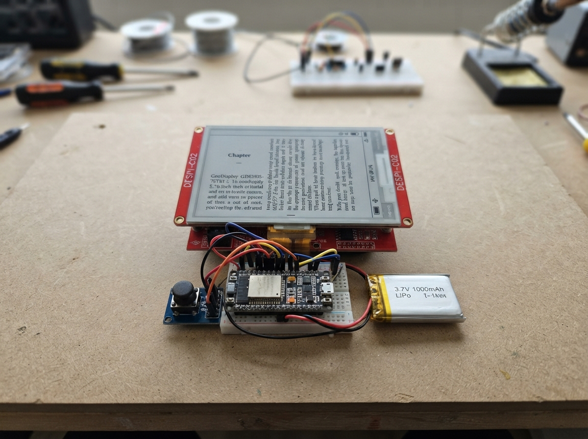
This project builds a functional e-reader interface on the ESP32 using a 5.76-inch e-paper display and five-direction navigation controls. The GooDisplay e-paper module provides crisp, low-power text and graphics rendering, while the DESPI-C02 adapter simplifies wiring to the microcontroller. A LiPo battery powers the entire system for portable reading sessions.
The guide provides a complete wiring diagram, parts list, and firmware with debounced button handling that runs independently of display refresh cycles. Assembly steps cover preparing the e-paper display, connecting the SPI interface and control lines, integrating the navigation button module, and safely connecting the battery. After following this guide, readers will have a working e-reader platform ready for custom book content and UI development.
Wiring diagram
Gather all the parts
Assemble it in 6 steps
1. Prepare the screen and adapter
With the board unplugged, slide the e-paper screen’s thin flex cable fully and straight into the DESPI-C02 adapter. Match the exposed metal contacts to the direction marked on the adapter, then close its latch gently if it has one.
- If the cable needs force, remove it and check its direction.
- Do not bend, crease, or pull the thin display flex cable; it can tear and permanently damage the screen.
2. Wire the e-paper adapter
Use short wires from the DESPI-C02 adapter to the labelled side headers on the LOLIN S3 Pro: adapter 3.3V → board 3V3 (power), adapter GND → board GND (ground), adapter SDI → GPIO11 (picture data), adapter SCK → GPIO12 (screen clock), adapter CS → GPIO10 (screen select), adapter D/C → GPIO15 (command or picture-data choice), adapter RES → GPIO16 (screen reset), and adapter BUSY → GPIO17 (screen-ready signal).
- Use the printed labels beside the pins, not the order of pins.
- Keep the wires short and do not connect the adapter 3.3V pin to 5V.
- Make sure 3.3V and GND are not swapped — swapped power can damage the display adapter or screen.
3. Wire the navigation controls
Connect the button module COM → a board GND pin (ground). Then connect UP → GPIO1 (move up), DWN → GPIO2 (move down), LFT → GPIO18 (previous page), RHT → GPIO4 (next page), MID → GPIO5 (open selected book), SET → GPIO6 (change text size), and RST → GPIO7 (return to the book list).
- Each button press connects its named pin to COM, so the COM-to-GND wire is required.
- A quick tap counts exactly once.
- Do not connect a module power pin to 5V; this project uses the button contacts and COM only.
4. No book card needed for this test
The button test does not read the microSD card. You can leave the card inserted or remove it while power is off.
5. Connect the battery safely
Check that the battery plug fits the LOLIN S3 Pro battery socket without force. Plug it in only with red on the positive contact and black on the negative contact; the board charges it when USB is connected.
- If the plug shape or wire order does not match, use a correctly wired adapter lead rather than forcing it.
- Reversed battery wiring can damage the board and make the battery dangerously hot. Never use a swollen, cut, or damaged battery.
6. Power and test the buttons
Check the wiring, plug the board into USB, and press Deploy. Wait for BUTTON TEST and READY on the screen. Press and release UP, DWN, LFT, RHT, MID, SET, and RST one at a time. The screen shows the last button name and press counts. Wait for each screen refresh before the next test. No books or microSD card are needed.
- The e-paper screen flashes during refresh; this is normal.
- Holding a button counts once. Release it before pressing again.
- Use RST on the button module, not the board reset button.
- Disconnect power before changing any wires.
Review all connections
1. Connections between "epaper_1" and "ESP32"
2. Connections between "nav_button_1" and "ESP32"
3. Connections between "battery_1" and "ESP32"
Deploy the firmware
#include <Arduino.h>
#include <SPI.h>
#include <GxEPD2_BW.h>
#include <gdeh/GxEPD2_576_GDEH0576T81.h>
#include <freertos/FreeRTOS.h>
#include <freertos/queue.h>
#include <freertos/task.h>

// Existing DESPI-C02 wiring is unchanged.
constexpr int EPD_SDI = 11, EPD_SCK = 12, EPD_CS = 10;
constexpr int EPD_D_C = 15, EPD_RES = 16, EPD_BUSY = 17;
constexpr int SD_CS = 46;
const int buttonPins[] = {1, 2, 18, 4, 5, 6, 7};
const char* const buttonNames[] = {"UP", "DWN", "LFT", "RHT", "MID", "SET", "RST"};
GxEPD2_BW<GxEPD2_576_GDEH0576T81, GxEPD2_576_GDEH0576T81::HEIGHT>
display(GxEPD2_576_GDEH0576T81(EPD_CS, EPD_D_C, EPD_RES, EPD_BUSY));
QueueHandle_t presses;
uint32_t counts[7] = {};
uint32_t total = 0;

// Scan independently so a screen refresh does not hide button presses.
void scanButtons(void*)
{
  bool raw[7], stable[7];
  uint32_t changed[7];
  for (int i = 0; i < 7; ++i) { raw[i] = stable[i] = HIGH; changed[i] = millis(); }
  for (;;) {
    uint32_t now = millis();
    for (uint8_t i = 0; i < 7; ++i) {
      bool value = digitalRead(buttonPins[i]);
      if (value != raw[i]) { raw[i] = value; changed[i] = now; }
      if (value != stable[i] && now - changed[i] >= 30) {
        stable[i] = value;
        if (value == LOW) xQueueSend(presses, &i, 0);
      }
    }
    vTaskDelay(pdMS_TO_TICKS(5));
  }
}

void drawTest(int last)
{
  display.setFullWindow();
  display.firstPage();
  do {
    display.fillScreen(GxEPD_WHITE);
    display.setTextColor(GxEPD_BLACK);
    display.setTextSize(3);
    display.setCursor(24, 30);
    display.print("BUTTON TEST");
    display.setTextSize(2);
    display.setCursor(24, 80);
    display.print("Last button pressed:");
    display.setTextSize(7);
    display.setCursor(24, 120);
    display.print(last < 0 ? "READY" : buttonNames[last]);
    display.setTextSize(2);
    display.setCursor(24, 210);
    display.print("Total presses: "); display.print(total);
    for (int i = 0; i < 7; ++i) {
      display.setCursor(24, 260 + i * 36);
      display.print(buttonNames[i]);
      display.print("  GPIO"); display.print(buttonPins[i]);
      display.print("  count: "); display.print(counts[i]);
    }
    display.setCursor(24, 560);
    display.print("Press and release any module button.");
    display.setCursor(24, 590);
    display.print("Wait for refresh before the next test.");
    display.setCursor(24, 620);
    display.print("Module RST is a test button, not reset.");
  } while (display.nextPage());
}

void setup()
{
  for (int pin : buttonPins) pinMode(pin, INPUT_PULLUP);
  // Keep the unused onboard microSD deselected on the shared SPI bus.
  pinMode(SD_CS, OUTPUT); digitalWrite(SD_CS, HIGH);
  pinMode(EPD_CS, OUTPUT); digitalWrite(EPD_CS, HIGH);
  pinMode(EPD_RES, OUTPUT); digitalWrite(EPD_RES, HIGH);
  SPI.begin(EPD_SCK, 13, EPD_SDI, EPD_CS);
  display.init(115200);
  display.setRotation(1);
  presses = xQueueCreate(32, sizeof(uint8_t));
  if (!presses) { for (;;) delay(1000); }
  if (xTaskCreate(scanButtons, "buttons", 2048, nullptr, 1, nullptr) != pdPASS) {
    for (;;) delay(1000);
  }
  drawTest(-1);
}

void loop()
{
  uint8_t button;
  if (xQueueReceive(presses, &button, pdMS_TO_TICKS(50)) == pdTRUE) {
    ++counts[button]; ++total;
    drawTest(button);
  }
}
Remix this project
Make it yours in one click
Open a full copy of this project in your own Schematik workspace, diagram, code, parts, and assembly steps included. Swap the sensor, add features, or redesign the whole thing with AI. The author's original stays untouched.