Community project
ESP32 TFT Dashboard
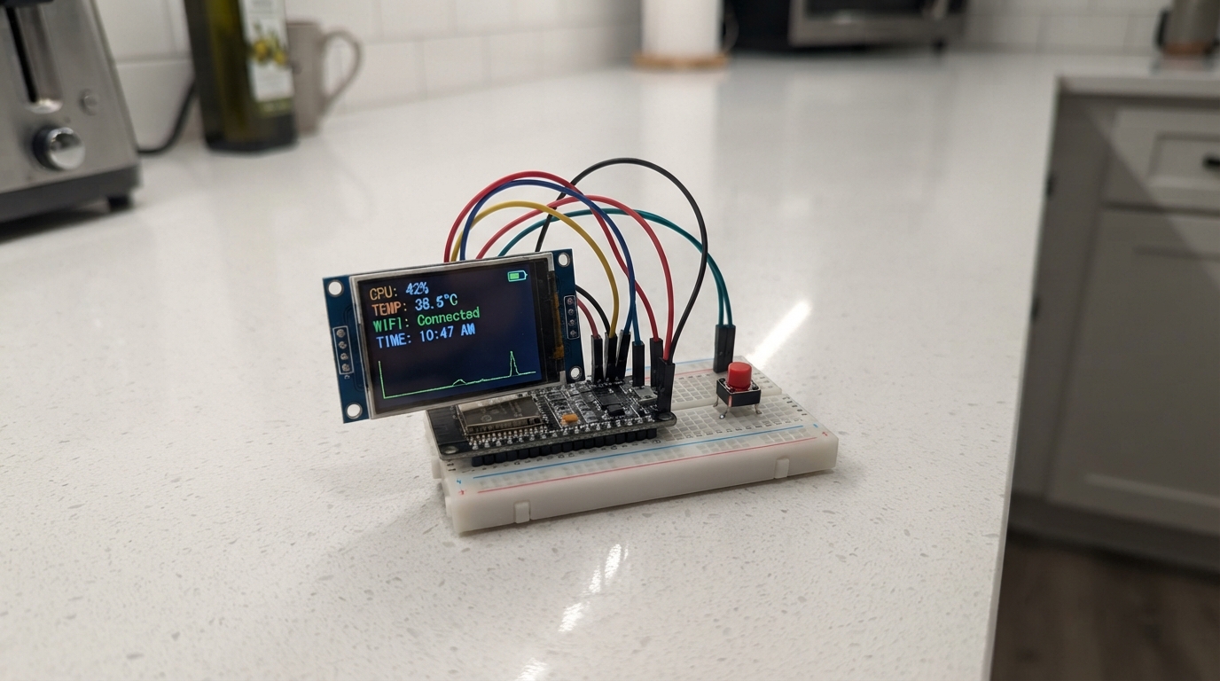
This project builds a low-power clock display using an ESP32 microcontroller and a 1.9-inch TFT screen. The display shows the current time fetched over Wi-Fi and enters deep sleep mode to conserve battery, waking only when the push button is pressed. The guide includes a complete wiring diagram, parts list, and step-by-step assembly instructions for connecting the display and button to the ESP32.
The firmware handles Wi-Fi connectivity, time synchronization, and sleep management, with the screen turning off after 20 seconds of inactivity. Builders will learn how to control a TFT display via SPI, implement button-based wake interrupts, and optimize power consumption on the ESP32 platform.
Wiring diagram

Gather all the parts
Assemble it in 4 steps
1. Ngắt nguồn trước khi nối dây
Rút cáp USB khỏi ESP32 trước khi cắm dây. Đặt ESP32 và màn hình TFT trên bàn sao cho bạn đọc được nhãn chân in trên hai bo mạch.
- Dùng dây Dupont ngắn giúp hình ảnh ổn định hơn khi màn hình dùng tốc độ cao.
- Không cấp nguồn khi đang đổi dây vì chạm nhầm chân nguồn có thể làm hỏng màn hình hoặc ESP32.
2. Nối nguồn và các dây màn hình
Nối TFT VCC → chân 3V3 của ESP32 (power), TFT GND → GND của ESP32 (ground), TFT SCL → GPIO18 (xung dữ liệu), TFT SDA → GPIO23 (dữ liệu), TFT RST → GPIO4 (đặt lại màn hình), TFT DC → GPIO2 (chọn lệnh hoặc hình ảnh), TFT CS → GPIO15 (chọn màn hình), và TFT BLK → GPIO32 (bật/tắt đèn nền).
- SCL và SDA ở đây là nhãn của màn hình SPI, không phải cặp dây cảm biến I2C.
- Kiểm tra kỹ chữ in cạnh chân TFT; một số bo mạch ghi SCK thay cho SCL và MOSI/DIN thay cho SDA.
- VCC của màn hình phải nối 3V3, không nối 5V, trừ khi bo mạch màn hình của bạn ghi rõ là chấp nhận 5V. Đảo VCC và GND có thể làm hỏng màn hình.
- GPIO2 và GPIO15 là chân khởi động đặc biệt của ESP32; không thêm điện trở kéo lên/kéo xuống hay thiết bị khác vào hai chân này.
3. Nối nút để đánh thức đồng hồ
Nối một chân của nút nhấn → GPIO27 (signal), chân còn lại → GND của ESP32 (ground). Nút không có cực nên hai chân này có thể đổi cho nhau; nếu là nút 4 chân, dùng hai chân nằm ở hai phía đối diện, không dùng hai chân cùng một phía.
- ESP32 tự giữ GPIO27 ở mức cao bên trong. Khi bạn nhấn nút, chân này chạm GND và đồng hồ thức dậy.
- Không nối nút sang 3V3; chương trình chờ nút kéo GPIO27 xuống GND để đánh thức.
4. Cấp nguồn và thiết lập Wi‑Fi lần đầu
Cắm ESP32 vào USB. Lần đầu, màn hình sẽ mở điểm Wi‑Fi tên ESP32-Clock-Setup trong khoảng ba phút; kết nối điện thoại vào điểm này với mật khẩu clocksetup rồi chọn Wi‑Fi nhà của bạn. Đồng hồ lấy giờ Việt Nam từ Internet, hiển thị khoảng 20 giây rồi tắt đèn nền và ngủ.
- Sau khi đã lưu Wi‑Fi, mỗi lần bấm nút ESP32 sẽ thức dậy, tự lấy giờ mới rồi lại ngủ.
- Nếu không thấy điểm thiết lập, bấm nút một lần để thử lại.
- Đừng rút nguồn trong khi ESP32 đang mở màn hình thiết lập Wi‑Fi; chờ nó hoàn tất hoặc hết thời gian chờ.
Review all connections
1. Connections between "tft_19" and "ESP32"
2. Connections between "wake_button" and "ESP32"
Deploy the firmware
#include <Arduino.h>
#include <SPI.h>
#include <WiFi.h>
#include <esp_sleep.h>

#if !defined(ESP32)
using gpio_num_t = int;
#endif

#define TFT_SCLK 18
#define TFT_MOSI 23
#define TFT_RST 4
#define TFT_DC 2
#define TFT_CS 15
#define TFT_BLK 32
#define WAKE_BUTTON 27


// Forward declarations
void command(uint8_t value);
void data(const uint8_t *values, size_t count);
void setWindow(uint16_t x, uint16_t y, uint16_t w, uint16_t h);
void fillRect(int x, int y, int w, int h, uint16_t color);
void initTft();
void drawDigit(int x, int y, int digit, uint16_t color);
void drawColon(int x, int y, uint16_t color);
void drawClock(const tm &timeInfo);
void showError();
bool connectAndGetTime(tm &timeInfo);
void sleepUntilButton();

constexpr uint16_t SW = 320;
constexpr uint16_t SH = 170;
constexpr uint32_t SCREEN_ON_MS = 20000;
constexpr uint32_t WIFI_TIMEOUT_MS = 20000;
const char *ssid = "Viettel";
const char *password = "0335814096";

constexpr uint16_t BLACK = 0x0000;
constexpr uint16_t WHITE = 0xFFFF;
constexpr uint16_t CYAN = 0x07FF;
constexpr uint16_t YELLOW = 0xFFE0;
constexpr uint16_t GREEN = 0x07E0;
constexpr uint16_t BLUE = 0x001F;
constexpr uint16_t RED = 0xF800;

void command(uint8_t value) {
  digitalWrite(TFT_DC, LOW);
  digitalWrite(TFT_CS, LOW);
  SPI.transfer(value);
  digitalWrite(TFT_CS, HIGH);
}

void data(const uint8_t *values, size_t count) {
  digitalWrite(TFT_DC, HIGH);
  digitalWrite(TFT_CS, LOW);
  SPI.writeBytes(values, count);
  digitalWrite(TFT_CS, HIGH);
}

void setWindow(uint16_t x, uint16_t y, uint16_t w, uint16_t h) {
  uint8_t values[] = {uint8_t(x >> 8), uint8_t(x), uint8_t((x + w - 1) >> 8), uint8_t(x + w - 1)};
  command(0x2A); data(values, sizeof(values));
  values[0] = y >> 8; values[1] = y; values[2] = (y + h - 1) >> 8; values[3] = y + h - 1;
  command(0x2B); data(values, sizeof(values));
  command(0x2C);
}

void fillRect(int x, int y, int w, int h, uint16_t color) {
  if (x < 0) { w += x; x = 0; }
  if (y < 0) { h += y; y = 0; }
  if (x + w > SW) w = SW - x;
  if (y + h > SH) h = SH - y;
  if (w <= 0 || h <= 0) return;
  setWindow(x, y, w, h);
  uint8_t block[64];
  for (size_t i = 0; i < sizeof(block); i += 2) { block[i] = color >> 8; block[i + 1] = color; }
  uint32_t remaining = uint32_t(w) * h;
  digitalWrite(TFT_DC, HIGH); digitalWrite(TFT_CS, LOW);
  while (remaining) { uint32_t pixels = remaining > 32 ? 32 : remaining; SPI.writeBytes(block, pixels * 2); remaining -= pixels; }
  digitalWrite(TFT_CS, HIGH);
}

void initTft() {
  pinMode(TFT_CS, OUTPUT); pinMode(TFT_DC, OUTPUT); pinMode(TFT_RST, OUTPUT);
  digitalWrite(TFT_CS, HIGH); digitalWrite(TFT_RST, LOW); delay(20); digitalWrite(TFT_RST, HIGH); delay(120);
  command(0x01); delay(150);
  command(0x11); delay(120);
  uint8_t madctl = 0x60; command(0x36); data(&madctl, 1);
  uint8_t mode = 0x55; command(0x3A); data(&mode, 1);
  command(0x21);
  command(0x29); delay(20);
  fillRect(0, 0, SW, SH, BLACK);
}

void drawDigit(int x, int y, int digit, uint16_t color) {
  static const uint8_t segments[] = {0x3F,0x06,0x5B,0x4F,0x66,0x6D,0x7D,0x07,0x7F,0x6F};
  const uint8_t s = segments[digit]; const int t = 8, l = 28;
  if (s & 0x01) fillRect(x + t, y, l, t, color);
  if (s & 0x02) fillRect(x + t + l, y + t, t, l, color);
  if (s & 0x04) fillRect(x + t + l, y + 2 * t + l, t, l, color);
  if (s & 0x08) fillRect(x + t, y + 2 * (t + l), l, t, color);
  if (s & 0x10) fillRect(x, y + 2 * t + l, t, l, color);
  if (s & 0x20) fillRect(x, y + t, t, l, color);
  if (s & 0x40) fillRect(x + t, y + t + l, l, t, color);
}

void drawColon(int x, int y, uint16_t color) { fillRect(x, y + 22, 8, 8, color); fillRect(x, y + 66, 8, 8, color); }

void drawClock(const tm &timeInfo) {
  fillRect(0, 0, SW, SH, BLACK);
  fillRect(0, 0, SW, 8, BLUE);
  int values[] = {timeInfo.tm_hour / 10, timeInfo.tm_hour % 10, timeInfo.tm_min / 10, timeInfo.tm_min % 10, timeInfo.tm_sec / 10, timeInfo.tm_sec % 10};
  int xs[] = {12, 58, 120, 166, 228, 274};
  for (int i = 0; i < 6; ++i) drawDigit(xs[i], 32, values[i], YELLOW);
  drawColon(106, 32, CYAN); drawColon(214, 32, CYAN);
  // Numeric date bars: day, month and four-digit year are intentionally omitted to keep the display driver self-contained.
  fillRect(44, 146, 232, 4, GREEN);
}

void showError() {
  fillRect(0, 0, SW, SH, BLACK);
  for (int i = 0; i < 5; ++i) fillRect(58 + i * 42, 40, 24, 80, RED);
}

bool connectAndGetTime(tm &timeInfo) {
  WiFi.mode(WIFI_STA);
  WiFi.begin(ssid, password);
  const uint32_t started = millis();
  while (WiFi.status() != WL_CONNECTED && millis() - started < WIFI_TIMEOUT_MS) delay(250);
  if (WiFi.status() != WL_CONNECTED) return false;
  configTzTime("ICT-7", "pool.ntp.org", "time.nist.gov");
  return getLocalTime(&timeInfo, 15000);
}

void sleepUntilButton() {
  WiFi.disconnect(true); WiFi.mode(WIFI_OFF);
  digitalWrite(TFT_BLK, LOW);
  esp_sleep_enable_ext0_wakeup(static_cast<gpio_num_t>(WAKE_BUTTON), 0);
  esp_deep_sleep_start();
}

void setup() {
  pinMode(WAKE_BUTTON, INPUT_PULLUP);
  pinMode(TFT_BLK, OUTPUT); digitalWrite(TFT_BLK, HIGH);
  SPI.begin(TFT_SCLK, -1, TFT_MOSI, TFT_CS);
  SPI.beginTransaction(SPISettings(40000000, MSBFIRST, SPI_MODE0));
  initTft();
  tm timeInfo;
  if (connectAndGetTime(timeInfo)) drawClock(timeInfo); else showError();
  delay(SCREEN_ON_MS);
  sleepUntilButton();
}

void loop() {}
Remix this project
Make it yours in one click
Open a full copy of this project in your own Schematik workspace — diagram, code, parts, and assembly steps included. Swap the sensor, add features, or redesign the whole thing with AI. The author's original stays untouched.
Related projects

Create A Complete Electrical Schematic Esp32 Sma
ESP32 · September 17, 2026Ayansh Agrawal
ESP32 Kare Ekran Projeleri
ESP32 · September 16, 2026Seref Ai
Component Qty --------------------------- ------
ESP32 · September 16, 2026Yathartha Chakrawal