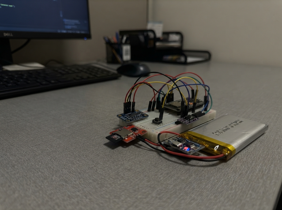
Community project
Component Qty --------------------------- ------

This sound-energy harvester captures acoustic vibrations through piezoelectric discs and stores the energy in a supercapacitor for later use. A bridge rectifier converts the AC output from the piezo elements into DC, while Zener diodes and resistors protect the storage circuit from overvoltage. The guide includes a complete wiring diagram, parts list, and step-by-step assembly instructions for building the energy-capture stage, protection network, and measurement circuit.
The ESP32 microcontroller reads the stored voltage via an ADS1115 16-bit ADC and displays real-time energy levels on an SSD1306 OLED screen. Firmware is provided to sample the supercapacitor voltage, calculate stored energy in joules, and show the charge state as a percentage of the safe operating limit. Builders will learn how to harvest energy from sound and vibration while keeping the storage system safe from electrical damage.
Wiring diagram

Gather all the parts
Assemble it in 7 steps
1. Prepare the piezo discs
Lay four piezo discs on thin aluminium or acrylic pieces that can flex from nearby sound. Solder two flexible wires to each disc, then use foam or rubber so each disc can bend slightly without its ceramic surface being crushed.
- Keep the leads short and add a small drop of glue where each wire leaves the disc so repeated bending does not tear the metal coating.
- Do not bend or press hard on the ceramic discs; cracked discs can have sharp edges and stop producing voltage.
2. Make the four-diode bridge
Build a bridge from d1 through d4. Join the unbanded end of d1 to the banded end of d2; this is the first piezo input. Join the unbanded end of d3 to the banded end of d4; this is the second piezo input. Join the banded ends of d1 and d3 to make bridge positive. Join the unbanded ends of d2 and d4 to make bridge negative, then connect that negative junction to ESP32 GND.
- The printed stripe marks each diode's banded end. Photograph the bridge before powering anything so you can check the stripe directions.
- A reversed diode will greatly reduce charging or stop the circuit from working.
3. Connect the disc array to the bridge
Connect every disc's P lead to the first bridge input: the d1 unbanded and d2 banded junction. Connect every disc's N lead to the second bridge input: the d3 unbanded and d4 banded junction. This places the discs in parallel, which is the safest starting arrangement.
- If you use more discs, connect each extra disc across these same two input junctions; do not connect them to the ESP32 pins.
- Piezo discs can make sharp voltage spikes when tapped, so keep all piezo wiring away from the ESP32 and connect only through the bridge and charging parts.
4. Add the protected energy store
Connect the bridge-positive junction to one end of the 1 kΩ charge_resistor. Connect its other end to the positive VPLUS terminal of supercap. Connect the banded end of clamp_zener to that same VPLUS point, and its unbanded end to GND. Connect supercap GND to ESP32 GND.
- The supercapacitor normally marks its positive terminal with a + symbol; check the marking before inserting it.
- Do not swap the supercapacitor terminals or bypass the 1 kΩ resistor — swapped power or uncontrolled charging can damage the capacitor.
5. Build the safe voltage-measuring divider
Connect one end of divider_top, the 100 kΩ resistor, to supercap VPLUS. Connect its other end to ADS1115 AIN0. Connect one end of divider_bottom, the other 100 kΩ resistor, to that same AIN0 point. Connect divider_bottom's other end to GND. The two resistors cut the voltage in half before it reaches the measurement module.
- Use a separate breadboard row for the AIN0 junction so the two resistor leads and AIN0 are firmly connected.
- Do not connect the supercapacitor positive terminal directly to AIN0 — a piezo spike or a fully charged capacitor could damage the measurement module.
6. Wire the ADS1115 and screen
Connect ADS1115 VDD to ESP32 3V3 (power), ADS1115 GND to ESP32 GND (ground), ADS1115 SDA to GPIO21 (data), ADS1115 SCL to GPIO22 (clock), and ADS1115 ADDR to GND. Connect OLED VCC to ESP32 3V3 (power), OLED GND to ESP32 GND (ground), OLED SDA to GPIO21 (data), and OLED SCL to GPIO22 (clock).
- The two modules share GPIO21 and GPIO22; this is expected. Make sure every ground wire joins the ESP32 GND rail.
- Make sure VCC and GND are not swapped on either module — swapped power can damage the screen or measurement module.
7. Test with sound and vibration
Place the piezo-disc diaphragm near a speaker or vibration source, plug the ESP32 into USB, and use Schematik's Deploy button. The screen reports capacitor voltage and the stored energy estimate; tapping or flexing the diaphragm should make the value rise gradually.
- Start with gentle tapping to prove the circuit. Loud airborne sound alone produces very little energy, so a resonant diaphragm or direct vibration coupling gives a clearer demonstration.
- This is an energy-harvesting demonstrator, not a practical power supply for the ESP32; leave the ESP32 powered from USB.
Review all connections
1. Connections between "piezo_1" and "ESP32"
2. Connections between "piezo_2" and "ESP32"
3. Connections between "piezo_3" and "ESP32"
4. Connections between "piezo_4" and "ESP32"
5. Connections between "d2" and "ESP32"
6. Connections between "d4" and "ESP32"
7. Connections between "d1" and "ESP32"
8. Connections between "d3" and "ESP32"
9. Connections between "charge_resistor" and "ESP32"
10. Connections between "clamp_zener" and "ESP32"
11. Connections between "supercap" and "ESP32"
12. Connections between "divider_top" and "ESP32"
13. Connections between "divider_bottom" and "ESP32"
14. Connections between "ads1115_1" and "ESP32"
15. Connections between "oled_1" and "ESP32"
Deploy the firmware
#include <Arduino.h>
#include <Wire.h>
#include <Adafruit_ADS1X15.h>
#include <Adafruit_GFX.h>
#include <Adafruit_SSD1306.h>


// Forward declarations
float readStoredVoltage();
void drawStatus(float storedVoltage);

constexpr int I2C_SDA_PIN = 21;
constexpr int I2C_SCL_PIN = 22;
constexpr uint8_t OLED_ADDRESS = 0x3C;
constexpr uint8_t ADS_ADDRESS = 0x48;
constexpr float DIVIDER_RATIO = 2.0f;  // two equal 100 kOhm resistors
constexpr float SUPERCAP_FARADS = 1.0f;
constexpr unsigned long SAMPLE_INTERVAL_MS = 500;

Adafruit_ADS1115 ads;
Adafruit_SSD1306 display(128, 64, &Wire, -1);

bool adsReady = false;
bool displayReady = false;
float lastShownVoltage = -1.0f;
unsigned long lastSampleAt = 0;

float readStoredVoltage() {
  // Gain one gives a +/-4.096 V ADC range. The divider halves the capacitor voltage.
  int16_t raw = ads.readADC_SingleEnded(0);
  float adcVolts = raw * 0.000125f;
  return adcVolts * DIVIDER_RATIO;
}

void drawStatus(float storedVoltage) {
  if (!displayReady) return;

  float energyJoules = 0.5f * SUPERCAP_FARADS * storedVoltage * storedVoltage;
  int percentOfSafeLimit = constrain((int)((storedVoltage / 5.1f) * 100.0f + 0.5f), 0, 100);

  display.clearDisplay();
  display.setTextColor(SSD1306_WHITE);
  display.setTextSize(1);
  display.setCursor(0, 0);
  display.println("Sound-energy harvester");
  display.drawFastHLine(0, 11, 128, SSD1306_WHITE);

  display.setTextSize(2);
  display.setCursor(0, 17);
  display.print(storedVoltage, 3);
  display.println(" V");

  display.setTextSize(1);
  display.setCursor(0, 42);
  display.print("Stored: ");
  display.print(energyJoules, 3);
  display.println(" J");
  display.setCursor(0, 54);
  display.print("Charge: ");
  display.print(percentOfSafeLimit);
  display.println("% of 5.1V");
  display.display();
}

void setup() {
  Serial.begin(115200);
  Wire.begin(I2C_SDA_PIN, I2C_SCL_PIN);

  displayReady = display.begin(SSD1306_SWITCHCAPVCC, OLED_ADDRESS);
  if (displayReady) {
    display.clearDisplay();
    display.setTextColor(SSD1306_WHITE);
    display.setTextSize(1);
    display.setCursor(0, 0);
    display.println("Starting harvester...");
    display.display();
  }

  adsReady = ads.begin(ADS_ADDRESS, &Wire);
  if (adsReady) {
    ads.setGain(GAIN_ONE);
    Serial.println("ADS1115 ready.");
  } else {
    Serial.println("ADS1115 not found at 0x48.");
  }

  if (!displayReady) {
    Serial.println("OLED not found at 0x3C.");
  }
}

void loop() {
  if (!adsReady) {
    delay(1000);
    return;
  }

  unsigned long now = millis();
  if (now - lastSampleAt < SAMPLE_INTERVAL_MS) return;
  lastSampleAt = now;

  float storedVoltage = readStoredVoltage();
  float energyJoules = 0.5f * SUPERCAP_FARADS * storedVoltage * storedVoltage;
  Serial.printf("Stored voltage: %.3f V, energy: %.3f J\n", storedVoltage, energyJoules);

  if (lastShownVoltage < 0.0f || fabsf(storedVoltage - lastShownVoltage) >= 0.005f) {
    drawStatus(storedVoltage);
    lastShownVoltage = storedVoltage;
  }
}
Remix this project
Make it yours in one click
Open a full copy of this project in your own Schematik workspace — diagram, code, parts, and assembly steps included. Swap the sensor, add features, or redesign the whole thing with AI. The author's original stays untouched.