Community project
Fail-Safe Engine Vent Lift
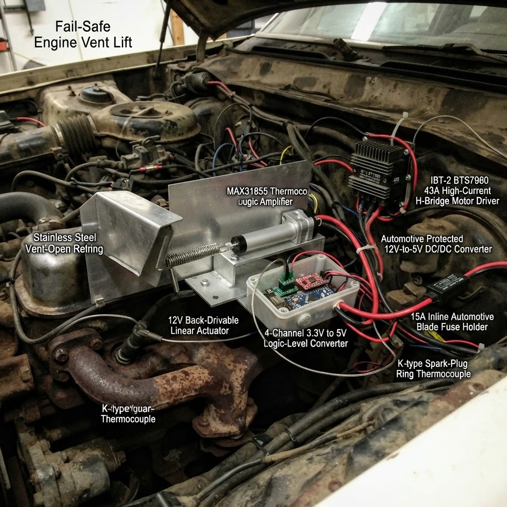
This fail-safe engine vent lift automatically opens an external vent flap when cylinder-head temperature exceeds 180°C, then closes it again below 150°C. The system uses a K-type thermocouple probe mounted on the cylinder head, an ESP32 microcontroller to monitor temperature and control a 12 V linear actuator, and a watchdog relay that forces the vent open if the controller loses power or crashes.
The guide provides a complete wiring diagram, full parts list with sourcing, and step-by-step assembly instructions including how to wire the thermocouple amplifier, motor driver, logic-level converter, and fused power distribution. Firmware is included with conservative temperature thresholds and safety timeouts. Before road use, the guide walks through proving the fail-open mechanism and verifying the watchdog relay triggers correctly.
Wiring diagram

Gather all the parts
Assemble it in 6 steps
1. Make the vent fail open without electricity
Build the vent flap with a solid hinge and a physical open stop. Bolt the fixed end of vent_actuator to a reinforced body bracket and pin its moving clevis to the vent_flap arm. Hook open_return_spring between the flap arm and a fixed body bracket so it pulls the flap all the way to its open stop whenever the actuator is not holding it closed.
- Before adding any wiring, disconnect the actuator and pull the flap closed by hand. Let go: the spring must open the flap fully every time.
- Choose a back-drivable actuator or an actuator specifically specified by its maker as compatible with the return spring. A typical self-locking actuator will defeat this safety feature.
- Do not use a spring that merely helps the flap move; it must reliably open the flap against dirt, vibration, and airflow. A vent that remains closed after a power failure can overheat the engine.
- Keep the flap outside the exhaust stream and clear of hot exhaust parts, moving belts, and the engine lid.
2. Fit the cylinder-head temperature probe
With the engine completely cold, remove the spark plug from the cylinder head you want to monitor and place the ring of cht_probe beneath that plug. Refit and torque the spark plug to the engine manufacturer’s specification. Route the two probe wires through heat sleeve and secure them away from plug leads, the fan belt, exhaust, and sharp sheet metal.
- Keep the thermocouple extension wire as a matched pair all the way to the sensor board; do not splice ordinary copper wire into either lead.
- Put the MAX31855 board in the sealed electronics enclosure, not in the hot engine bay.
- Do not work on the spark plug or head with a hot engine — the plug and surrounding metal can burn you.
- Keep the thermocouple wires away from ignition leads because ignition noise can corrupt temperature readings.
3. Mount the protected electronics
Mount the ESP32, cht_interface, logic_shifter, watchdog_relay, and auto_buck inside a gasketed, vibration-isolated enclosure in a cool, dry location. Mount motor_driver on a metal heat-spreading plate inside a protected location, with its heavy motor wires kept separate from the small sensor wires.
- Use crimp terminals, strain relief, and automotive-rated wire. Label both ends before closing the enclosure.
- Bring the chassis ground return to a clean bare-metal body point with a star washer, then protect that point from corrosion.
- Do not mount the ESP32 or the unsealed driver board where engine heat, road spray, or fuel vapour can reach it.
- Do not share thin sensor wiring with the actuator current path; a loose high-current connection can overheat.
4. Wire the temperature reader and control signals
Connect cht_probe positive lead to cht_interface T+ (temperature signal), and negative lead to cht_interface T- (temperature signal). Wire cht_interface VCC to ESP32 3V3 (power), GND to ESP32 GND (ground), SCK to GPIO18 (clock), SO to GPIO19 (data), and CS to GPIO4 (select). Wire logic_shifter LV to 3V3 (power), HV to 5V (power), and GND to GND (ground). Wire LV1 to GPIO25 (close signal), LV2 to GPIO26 (open signal), and LV3 to GPIO27 (watchdog heartbeat). Connect HV1 to motor_driver RPWM (close command), HV2 to motor_driver LPWM (open command), and HV3 to watchdog_relay TRIG (heartbeat).
- All low-voltage modules need the same ground connection or their signals will not have a reliable reference.
- Use twisted pair or shielded cable for the thermocouple run; connect any cable shield at the enclosure end only.
- Make sure the MAX31855 board receives 3.3 V, not 5 V — swapped or excessive power can damage it.
- GPIO4 is used as a flexible select signal rather than a fixed SPI pin; this is normal on this ESP32, but check the first temperature reading during bench testing.
5. Wire the fused vehicle and actuator power
From an ignition-switched 12 V feed, wire the battery side to power_fuse Battery in (power). Wire power_fuse Protected out to auto_buck VIN+ (power) and watchdog_relay COM (power). Wire auto_buck VIN- to chassis ground (ground), 5V OUT to the ESP32 VIN pin, motor_driver VCC, motor_driver R_EN, motor_driver L_EN, logic_shifter HV, and watchdog_relay VCC (power). Connect every listed low-voltage ground to the same chassis-ground return (ground). Wire watchdog_relay NO to motor_driver B+ (actuator power), motor_driver B- to chassis ground (ground), M+ to vent_actuator Motor lead A (motor), and M- to vent_actuator Motor lead B (motor).
- Place the inline fuse as close as practical to the point where the new 12 V feed is taken.
- Use wire gauge and a fuse value based on the actuator manufacturer’s measured peak current; 15 A is only the starting design value for an actuator drawing under 5 A.
- Disconnect the vehicle battery while installing the new 12 V feed. An unfused wire can start a fire if it rubs through on metal.
- Do not power the actuator from the ESP32 or its small USB connector. The actuator needs its own fused 12 V path.
6. Prove the safety action before road use
With the vehicle safely parked and the engine off, power the system. Confirm the vent first moves toward open. Then remove the fuse or unplug the controller: watchdog_relay must drop out and open_return_spring must pull vent_flap fully open. Reconnect power and use a controlled warm-air test at the thermocouple ring only after the mechanism has passed the no-power test.
- If the first powered movement goes the wrong way, disconnect vehicle power and swap the two actuator wires at motor_driver M+ and M-.
- Recheck the vent after driving on a rough road; vibration can loosen brackets and clevis pins.
- Never test this system by deliberately overheating the engine. Use the sensor reading and a safe bench heat source first.
- Do not drive the car until removing electrical power reliably leaves the vent fully open.
Review all connections
1. Connections between "cht_probe" and "ESP32"
2. Connections between "cht_interface" and "ESP32"
3. Connections between "motor_driver" and "ESP32"
4. Connections between "logic_shifter" and "ESP32"
5. Connections between "vent_actuator" and "ESP32"
6. Connections between "open_return_spring" and "ESP32"
7. Connections between "power_fuse" and "ESP32"
8. Connections between "auto_buck" and "ESP32"
9. Connections between "vent_flap" and "ESP32"
10. Connections between "watchdog_relay" and "ESP32"
Deploy the firmware
#include <Arduino.h>
#include <Adafruit_MAX31855.h>
#include <math.h>

// Matches the actual wires in the project.

// Hoisted type definitions
enum VentState { OPEN, CLOSED, MOVING_OPEN, MOVING_CLOSED };


// Forward declarations
void stopActuator();
void startOpening();
void startClosing();
void finishMotionIfDue();
void sendHeartbeat();
void requestSafeOpen();
void evaluateTemperature();

constexpr int THERMO_SCK_PIN = 18;
constexpr int THERMO_CS_PIN = 4;
constexpr int THERMO_SO_PIN = 19;
constexpr int CLOSE_PWM_PIN = 25;
constexpr int OPEN_PWM_PIN = 26;
constexpr int HEARTBEAT_PIN = 27;

// Conservative cylinder-head-temperature limits for the external auxiliary vent.
constexpr float OPEN_AT_C = 180.0F;
constexpr float CLOSE_BELOW_C = 150.0F;
constexpr unsigned long SAMPLE_INTERVAL_MS = 1000;
constexpr unsigned long HEARTBEAT_INTERVAL_MS = 100;
// 100 mm at 5 mm/s takes 20 seconds; this adds a small margin for linkage travel.
constexpr unsigned long FULL_TRAVEL_MS = 22000;
constexpr unsigned long STARTUP_OPEN_MS = 5000;
constexpr uint8_t DRIVE_PWM = 255;

Adafruit_MAX31855 thermocouple(THERMO_SCK_PIN, THERMO_CS_PIN, THERMO_SO_PIN);


VentState ventState = OPEN;
unsigned long motionStartedAt = 0;
unsigned long lastSampleAt = 0;
unsigned long lastHeartbeatAt = 0;
unsigned long startupAt = 0;
bool startupOpening = true;

void stopActuator() {
  analogWrite(CLOSE_PWM_PIN, 0);
  analogWrite(OPEN_PWM_PIN, 0);
}

void startOpening() {
  // If this moves the flap closed during the first bench test, swap the two motor leads at M+ and M-.
  analogWrite(CLOSE_PWM_PIN, 0);
  analogWrite(OPEN_PWM_PIN, DRIVE_PWM);
  ventState = MOVING_OPEN;
  motionStartedAt = millis();
}

void startClosing() {
  analogWrite(OPEN_PWM_PIN, 0);
  analogWrite(CLOSE_PWM_PIN, DRIVE_PWM);
  ventState = MOVING_CLOSED;
  motionStartedAt = millis();
}

void finishMotionIfDue() {
  if ((ventState == MOVING_OPEN || ventState == MOVING_CLOSED) &&
      millis() - motionStartedAt >= FULL_TRAVEL_MS) {
    bool wasOpening = (ventState == MOVING_OPEN);
    stopActuator();
    ventState = wasOpening ? OPEN : CLOSED;
  }
}

void sendHeartbeat() {
  // The external watchdog must see regular transitions; loss of this signal removes actuator power.
  if (millis() - lastHeartbeatAt >= HEARTBEAT_INTERVAL_MS) {
    digitalWrite(HEARTBEAT_PIN, !digitalRead(HEARTBEAT_PIN));
    lastHeartbeatAt = millis();
  }
}

void requestSafeOpen() {
  if (ventState != OPEN && ventState != MOVING_OPEN) {
    startOpening();
  }
}

void evaluateTemperature() {
  double reading = thermocouple.readCelsius();
  if (isnan(reading)) {
    // A disconnected, damaged, or unreadable head sensor must never leave the vent closed.
    requestSafeOpen();
    return;
  }

  float headC = static_cast<float>(reading);
  if (headC >= OPEN_AT_C) {
    requestSafeOpen();
  } else if (headC <= CLOSE_BELOW_C && ventState != CLOSED && ventState != MOVING_CLOSED) {
    startClosing();
  }
  // Between 150 C and 180 C, leave the vent where it is. This prevents repeated cycling.
}

void setup() {
  pinMode(CLOSE_PWM_PIN, OUTPUT);
  pinMode(OPEN_PWM_PIN, OUTPUT);
  pinMode(HEARTBEAT_PIN, OUTPUT);
  stopActuator();
  digitalWrite(HEARTBEAT_PIN, LOW);
  thermocouple.begin();
  startupAt = millis();

  // Begin by trying to open. The spring is the real fail-safe if this electronics path has failed.
  startOpening();
}

void loop() {
  sendHeartbeat();
  finishMotionIfDue();

  if (startupOpening) {
    if (millis() - startupAt >= STARTUP_OPEN_MS) {
      stopActuator();
      ventState = OPEN;
      startupOpening = false;
    }
    return;
  }

  if (millis() - lastSampleAt >= SAMPLE_INTERVAL_MS) {
    lastSampleAt = millis();
    evaluateTemperature();
  }
}
Remix this project
Make it yours in one click
Open a full copy of this project in your own Schematik workspace — diagram, code, parts, and assembly steps included. Swap the sensor, add features, or redesign the whole thing with AI. The author's original stays untouched.