Community project
Heavy-Lift Tracked Drone Platform
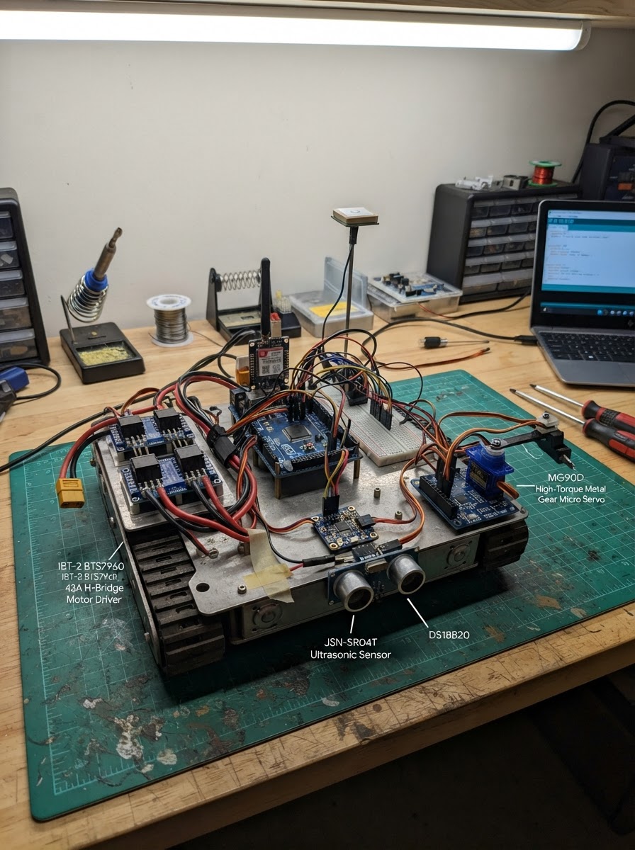
This guide builds a long-range amphibious tracked UGV (unmanned ground vehicle) capable of autonomous cargo delivery over 4G LTE with real-time telemetry. The platform combines dual 24V track motors controlled via high-current H-bridges, an internal combustion engine throttle servo, and comprehensive environmental sensing including GPS navigation, 9-axis IMU, waterproof ultrasonic obstacle detection, and engine temperature monitoring.
The complete guide includes a wiring diagram connecting the ESP32-S3 controller to motor drivers, the SIM7600 4G modem, u-blox GPS receiver, ICM-20948 IMU, servo driver, ultrasonic sensors, temperature probe, and bilge pump relay. Assembly steps cover power distribution, sensor calibration, and firmware upload. The provided Arduino sketch implements motor control, LTE connectivity, GPS waypoint navigation, and autonomous obstacle avoidance with bilge pump activation.
Wiring diagram

Gather all the parts
Assemble it in 12 steps
1. Prepare the 24V Power Distribution Bus
Mount the 24V LiFePO4 battery pack securely in the chassis with its terminals accessible. Run heavy-gauge cable (minimum 10 AWG / 6 mm²) from BAT+ to a 60A blade fuse, then to a power distribution bus bar. Run BAT- to a common GND bus bar. Connect the LM2596 buck converter: VIN+ from the 24V bus (via 5A inline fuse), VIN- to GND bus bar. Adjust the LM2596 trimmer potentiometer with a multimeter until VOUT+ reads exactly 5.0V before connecting any loads.
- Use ring terminals and heat-shrink on all high-current connections.
- A master kill switch on the 24V line is strongly recommended for safety.
- Verify 5V output with a multimeter before proceeding to logic components.
- NEVER connect motor B+ wires to the 5V logic rail — the IBT-2 motor supply is directly from the 24V bus.
- Reverse polarity will destroy all electronics instantly.
2. Mount and Wire the IBT-2 Motor Drivers
Mount both IBT-2 BTS7960 modules on the chassis with good ventilation or heatsinks. Connect B+ of each IBT-2 to the 24V bus bar (via separate 50A fuses), and B- to the GND bus bar. Connect M+ and M- of ibt2_left to the left track motor terminals; repeat for ibt2_right and the right track motor. Connect VCC of each IBT-2 to the 5V rail and GND to the GND bus bar. RPWM, LPWM, R_EN, L_EN signal lines go to the ESP32-S3 as per pin assignments (see wiring table).
- Use twisted pair or shielded cable for motor leads to reduce EMI near the ESP32.
- Bolt down the IBT-2 modules — vibration from tracks can loosen terminal screws.
- IBT-2 logic is 5V. ESP32-S3 is 3.3V. Add a 10kΩ/20kΩ voltage divider on RPWM, LPWM, R_EN, L_EN signal lines: ESP32 GPIO → 10kΩ → IBT-2 input; IBT-2 input → 20kΩ → GND. This brings 3.3V logic safely into the 5V IBT-2 input range.
3. Install the ESP32-S3 DevKitC-1 Controller
Mount the ESP32-S3-DevKitC-1 on a DIN rail or standoff bracket inside a sealed IP65 electronics enclosure. Power the board by connecting the 5V rail to the VIN pin and GND to GND. Connect all signal wires from the IBT-2 drivers, relay, sensors, and SIM module to their respective GPIOs per the wiring table.
- Use a sealed electronics enclosure (IP65 or better) rated for outdoor and underwater-splash environments.
- Cable glands are essential where wires enter the enclosure.
4. Wire the SIM7600 4G LTE Module
Mount the SIM7600 module with its LTE antenna on the exterior of the chassis for best signal. Install a SIM card with an active data plan. Power the SIM7600 from the 5V rail (it needs up to 2A during TX bursts — use a dedicated LM2596 output or an AMS1117-5V linear regulator on the 24V bus). Connect TXD→GPIO44, RXD→GPIO43, PWRKEY→GPIO21, RESET→GPIO38. The SIM7600 UART is 3.3V-compatible on most breakout boards.
- The SIM7600 is 3.3V tolerant on most breakout boards — check your specific module's logic level.
- Keep the LTE antenna cable short and route away from motor PWM wiring.
- SIM7600 can draw 2A+ in transmit bursts. Ensure its power supply can sustain this without voltage drop below 4.5V.
5. Wire the u-blox NEO-M8N GPS
Mount the GPS module and its antenna on the highest external point of the UGV (top of cargo platform) for clear sky view. Connect VCC to 3.3V rail, GND to GND bus, TX to GPIO39 (ESP32 RX2), RX to GPIO40 (ESP32 TX2). The GPS UART runs at 9600 baud.
- Keep the GPS antenna cable away from IBT-2 motor PWM wiring and the LTE antenna.
- Allow 60–90 seconds for first GPS fix in open sky conditions.
6. Install the ICM-20948 IMU and PCA9685 (I2C Bus)
Both the ICM-20948 IMU and the PCA9685 PWM expander share the I2C bus (GPIO8 SDA, GPIO9 SCL). Mount the IMU at the geometric center of the UGV chassis, aligned with the vehicle axes. Connect VIN (ICM-20948) and VCC (PCA9685) to 3.3V, both GND to GND bus, and SDA/SCL to GPIO8/GPIO9. The INT pin of the ICM-20948 goes to GPIO42. The PCA9685 V+ rail pin goes to 5V for servo power.
- Add 4.7kΩ pull-up resistors on SDA and SCL lines if I2C communication is unstable — one pair serves all I2C devices on the bus.
- The ICM-20948 default I2C address is 0x68; PCA9685 default is 0x40 — no conflict.
7. Connect the ICE Throttle Servo
Mechanically link the MG90D servo to the ICE throttle cable or carburetor lever arm. The servo signal wire connects to PCA9685 channel 0 (PWM0). VCC and GND of the servo connect directly to the 5V rail and GND. Test servo travel carefully before linking to the engine — the idle position (SERVO_IDLE_US=700µs) and full throttle (SERVO_MAX_THR=2200µs) constants in firmware may need adjustment for your specific engine.
- Test servo end-stops WITHOUT the engine running first. Over-travel can damage the carburetor linkage.
8. Wire the 3× JSN-SR04T Waterproof Ultrasonics
Mount one JSN-SR04T sensor at the front center, one on the left side, and one on the right side of the UGV hull, facing outward at bumper height. Route the cables to the electronics enclosure. Connect: Front → TRIG=GPIO15, ECHO=GPIO16; Left → TRIG=GPIO17, ECHO=GPIO18; Right → TRIG=GPIO41, ECHO=GPIO47. All sensors share the 5V rail and GND bus.
- The JSN-SR04T sealed transducer cable is rated for wet environments — route it through a cable gland into the enclosure.
- Minimum detection range is 25cm — the firmware stop threshold of 40cm provides a safe margin.
9. Wire the DS18B20 Engine Temperature Sensor
Use the waterproof stainless-steel DS18B20 probe variant. Attach the probe to the engine block or exhaust manifold cooling jacket with a thermal clamp. Connect VCC to 3.3V, GND to GND, DATA to GPIO48. Solder a 4.7kΩ resistor between the 3.3V rail and the DATA wire at the PCB/breadboard connection point (this is the required OneWire pull-up — NOT on a separate GPIO, just a wire bridge).
- The waterproof DS18B20 probe is rated to 125°C — sufficient for monitoring a small air-cooled ICE.
- The firmware shuts throttle at 95°C — verify this threshold matches your engine's limits.
10. Install Bilge Relay and Pump
Mount the 5V relay module inside the main electronics enclosure. Connect IN to GPIO10 (active-low: LOW = pump ON). VCC to 5V, GND to GND. Wire the relay COM to the 12V auxiliary bus positive, and the NO terminal to the bilge pump motor positive terminal. The bilge pump negative wire returns to GND. Place the bilge pump at the lowest point of the hull.
- The bilge pump's 12V supply must be fused (10A). The relay is NOT rated for 24V — use the 12V auxiliary bus or a voltage divider from 24V.
11. Wire and Position the ESP32-CAM Module
Mount the AI-Thinker ESP32-CAM in a waterproof IP65 dome camera housing with a wide-angle lens. Power it from the 5V rail (VCC=5V, GND=GND). The ESP32-CAM operates as a standalone WiFi camera node — flash it separately with the RTSP streaming sketch (see firmware notes). It streams video over its built-in WiFi to the SIM7600 4G hotspot or a co-located router.
- Use a 120° wide-angle OV2640 lens replacement for panoramic coverage.
- For true panoramic 360° coverage, mount three ESP32-CAM modules at 120° intervals around the cargo platform.
- The ESP32-CAM needs a stable 5V supply; use a separate 5V regulator output if your LM2596 is loaded near its current limit.
12. Final Checks and Sealing
Before sealing the electronics enclosure: (1) Measure 5V rail with multimeter — should be 4.9–5.1V under load. (2) Verify 3.3V rail. (3) Confirm all GPIO wires are firmly terminated. (4) Apply silicone sealant around all cable glands. (5) Apply conformal coating to all PCBs for moisture protection. (6) Test each track motor individually by running the firmware in manual test mode (serial commands) before enabling autonomous navigation.
- Run a bench power-up with the track motors disconnected first — verify GPS lock, IMU readings, and 4G connection before full assembly.
- Label all wiring harnesses with cable markers for future maintenance.
- Never test autonomous navigation in an enclosed space. Always test in open terrain with a human override (emergency kill switch) in hand.
Review all connections
1. Connections between "main_battery" and "ESP32"
2. Connections between "buck_5v" and "ESP32"
3. Connections between "ibt2_left" and "ESP32"
4. Connections between "ibt2_right" and "ESP32"
5. Connections between "track_motor_left" and "ESP32"
6. Connections between "track_motor_right" and "ESP32"
7. Connections between "sim7600" and "ESP32"
8. Connections between "gps" and "ESP32"
9. Connections between "imu" and "ESP32"
10. Connections between "pca9685" and "ESP32"
11. Connections between "throttle_servo" and "ESP32"
12. Connections between "sonar_front" and "ESP32"
13. Connections between "sonar_left" and "ESP32"
14. Connections between "sonar_right" and "ESP32"
15. Connections between "temp_sensor" and "ESP32"
16. Connections between "bilge_relay" and "ESP32"
17. Connections between "bilge_pump" and "ESP32"
18. Connections between "esp32cam" and "ESP32"
Deploy the firmware
#include <Arduino.h>
// ============================================================
//  Amphibious Tracked UGV — Main Controller Firmware
//  Board  : ESP32-S3-DevKitC-1
//  Author : Schematik
//  Purpose: Long-range 4G-telemetry cargo delivery UGV
//           with dual-track drive, ICE throttle, GPS nav,
//           9-DoF IMU, waterproof ultrasonics, bilge pump,
//           and engine-temp monitoring.
// ============================================================

// ---- Modem selection (must come before TinyGSM) -----------
#define TINY_GSM_MODEM_SIM7600
#include <TinyGsmClient.h>

#include <Wire.h>
#include <Adafruit_ICM20948.h>
#include <Adafruit_Sensor.h>
#include <Adafruit_PWMServoDriver.h>
#include <OneWire.h>
#include <DallasTemperature.h>
#include <NewPing.h>
#include <TinyGPSPlus.h>
#include <HardwareSerial.h>

// ---- Pin definitions (match set_wiring exactly) -----------
#define IBT2_L_RPWM   1
#define IBT2_L_LPWM   2
#define IBT2_L_R_EN   3
#define IBT2_L_L_EN   4
#define IBT2_R_RPWM   5
#define IBT2_R_LPWM   6
#define IBT2_R_R_EN   7
#define IBT2_R_L_EN   14
#define SIM_PWRKEY    21
#define SIM_RESET     38
#define GPS_RX_PIN    39   // UART2 RX ← GPS TX
#define GPS_TX_PIN    40   // UART2 TX → GPS RX
#define IMU_INT       42
#define SONAR_F_TRIG  15
#define SONAR_F_ECHO  16
#define SONAR_L_TRIG  17
#define SONAR_L_ECHO  18
#define SONAR_R_TRIG  41
#define SONAR_R_ECHO  47
#define BILGE_RELAY   10
#define ONEWIRE_BUS   48

// ---- UART assignments ------------------------------------
#define SIM_SERIAL_NUM  1   // UART1 → SIM7600 (GPIO43/44)
#define GPS_SERIAL_NUM  2   // UART2 → NEO-M8N (GPIO39/40)

// ---- Obstacle thresholds (cm) ----------------------------
#define OBSTACLE_STOP_CM    40
#define OBSTACLE_STEER_CM   80
#define SONAR_MAX_CM       400

// ---- IBT-2 PWM channel parameters -----------------------
#define PWM_FREQ_HZ      15000  // 15 kHz motor PWM
#define PWM_RESOLUTION     8    // 8-bit: 0-255

// ---- PCA9685 servo channels (ICE throttle) --------------
#define PCA_THROTTLE_CH   0
#define SERVO_MIN_US    500
#define SERVO_MAX_US   2500
#define SERVO_IDLE_US   700   // ~idle throttle
#define SERVO_MAX_THR  2200   // full throttle

// ---- APN for SIM7600 (update for your carrier) ----------
#define MODEM_APN       "internet"
#define MODEM_USER      ""
#define MODEM_PASS      ""
#define TELEMETRY_HOST  "ugv.local"   // Replace with your server IP / MQTT broker
#define TELEMETRY_PORT  1883

// ---- Temperature safety ---------------------------------
#define ENGINE_TEMP_MAX_C  95.0f   // shut throttle above this
#define BILGE_TEMP_TRIG_C  70.0f   // not used for bilge; reserved

// ====== Object instantiation ============================

// UART ports

// Hoisted type definitions
struct Waypoint { double lat; double lon; };


// Forward declarations
void setTrack(int rpwmPin, int lpwmPin, int renPin, int lenPin, int speed);
void driveForward(int spd);
void driveReverse(int spd);
void driveStop();
void turnLeft(int spd);
void turnRight(int spd);
void setThrottle(int microseconds);
bool modemInit();
void sendTelemetry();
void updateGPS();
void updateIMU();
bool obstacleCheck();
float bearingTo(double lat2, double lon2);
float distanceTo(double lat2, double lon2);
void navigateWaypoints();
void updateBilge();

HardwareSerial SimSerial(SIM_SERIAL_NUM);
HardwareSerial GpsSerial(GPS_SERIAL_NUM);

// Modem & GSM client
TinyGsm       modem(SimSerial);
TinyGsmClient gsmClient(modem);

// GPS
TinyGPSPlus gps;

// IMU
Adafruit_ICM20948 icm;

// PCA9685
Adafruit_PWMServoDriver pwm = Adafruit_PWMServoDriver(0x40);

// OneWire / DS18B20
OneWire           oneWire(ONEWIRE_BUS);
DallasTemperature tempSensor(&oneWire);

// Ultrasonics
NewPing sonarFront(SONAR_F_TRIG, SONAR_F_ECHO, SONAR_MAX_CM);
NewPing sonarLeft (SONAR_L_TRIG, SONAR_L_ECHO, SONAR_MAX_CM);
NewPing sonarRight(SONAR_R_TRIG, SONAR_R_ECHO, SONAR_MAX_CM);

// ====== State variables ==================================
float  engineTempC     = 0.0f;
float  imuRoll         = 0.0f;
float  imuPitch        = 0.0f;
double gpsLat          = 0.0;
double gpsLon          = 0.0;
float  gpsSpeedKmh     = 0.0f;
int    distFront       = SONAR_MAX_CM;
int    distLeft        = SONAR_MAX_CM;
int    distRight       = SONAR_MAX_CM;
bool   bilgeActive     = false;
bool   modemConnected  = false;

// Waypoint list (lat/lon pairs — extend as needed)

const Waypoint WAYPOINTS[] = {
    {48.8588443,  2.2943506},   // Example: Eiffel Tower
    {48.8606111,  2.3354553},   // Example: Louvre
};
const int   NUM_WAYPOINTS = sizeof(WAYPOINTS) / sizeof(WAYPOINTS[0]);
int         currentWaypoint = 0;
bool        autonomousMode  = false;

// ====== IBT-2 helper functions ===========================

// Set track speed: speed -255 (full reverse) to +255 (full forward)
void setTrack(int rpwmPin, int lpwmPin, int renPin, int lenPin, int speed) {
    digitalWrite(renPin, HIGH);
    digitalWrite(lenPin, HIGH);
    if (speed > 0) {
        ledcWrite(rpwmPin, speed);
        ledcWrite(lpwmPin, 0);
    } else if (speed < 0) {
        ledcWrite(rpwmPin, 0);
        ledcWrite(lpwmPin, -speed);
    } else {
        ledcWrite(rpwmPin, 0);
        ledcWrite(lpwmPin, 0);
    }
}

void driveForward(int spd)  { setTrack(IBT2_L_RPWM, IBT2_L_LPWM, IBT2_L_R_EN, IBT2_L_L_EN,  spd);
                               setTrack(IBT2_R_RPWM, IBT2_R_LPWM, IBT2_R_R_EN, IBT2_R_L_EN,  spd); }
void driveReverse(int spd)  { setTrack(IBT2_L_RPWM, IBT2_L_LPWM, IBT2_L_R_EN, IBT2_L_L_EN, -spd);
                               setTrack(IBT2_R_RPWM, IBT2_R_LPWM, IBT2_R_R_EN, IBT2_R_L_EN, -spd); }
void driveStop()            { setTrack(IBT2_L_RPWM, IBT2_L_LPWM, IBT2_L_R_EN, IBT2_L_L_EN,  0);
                               setTrack(IBT2_R_RPWM, IBT2_R_LPWM, IBT2_R_R_EN, IBT2_R_L_EN,  0); }
void turnLeft(int spd)      { setTrack(IBT2_L_RPWM, IBT2_L_LPWM, IBT2_L_R_EN, IBT2_L_L_EN, -spd);
                               setTrack(IBT2_R_RPWM, IBT2_R_LPWM, IBT2_R_R_EN, IBT2_R_L_EN,  spd); }
void turnRight(int spd)     { setTrack(IBT2_L_RPWM, IBT2_L_LPWM, IBT2_L_R_EN, IBT2_L_L_EN,  spd);
                               setTrack(IBT2_R_RPWM, IBT2_R_LPWM, IBT2_R_R_EN, IBT2_R_L_EN, -spd); }

// ====== ICE Throttle via PCA9685 =========================
void setThrottle(int microseconds) {
    microseconds = constrain(microseconds, SERVO_MIN_US, SERVO_MAX_US);
    int pulse = map(microseconds, 0, 20000, 0, 4096);
    pwm.setPWM(PCA_THROTTLE_CH, 0, pulse);
}

// ====== Modem setup =====================================
bool modemInit() {
    Serial.println("[LTE] Powering modem...");
    pinMode(SIM_PWRKEY, OUTPUT);
    pinMode(SIM_RESET,  OUTPUT);
    digitalWrite(SIM_RESET, LOW);
    digitalWrite(SIM_PWRKEY, LOW);
    delay(1000);
    digitalWrite(SIM_PWRKEY, HIGH);
    delay(2000);
    digitalWrite(SIM_PWRKEY, LOW);
    delay(3000);

    SimSerial.begin(115200, SERIAL_8N1, 44, 43); // RX=GPIO44, TX=GPIO43
    delay(500);
    if (!modem.restart()) {
        Serial.println("[LTE] Modem restart failed");
        return false;
    }
    Serial.print("[LTE] Modem: ");
    Serial.println(modem.getModemInfo());

    if (!modem.waitForNetwork(30000)) {
        Serial.println("[LTE] Network timeout");
        return false;
    }
    if (!modem.gprsConnect(MODEM_APN, MODEM_USER, MODEM_PASS)) {
        Serial.println("[LTE] GPRS connect failed");
        return false;
    }
    Serial.print("[LTE] IP: ");
    Serial.println(modem.localIP());
    return true;
}

// ====== Telemetry JSON uplink ===========================
void sendTelemetry() {
    if (!modemConnected) return;
    if (!gsmClient.connect(TELEMETRY_HOST, TELEMETRY_PORT)) {
        Serial.println("[TEL] Server connect failed");
        return;
    }
    char payload[320];
    snprintf(payload, sizeof(payload),
        "{\"lat\":%.6f,\"lon\":%.6f,\"spd\":%.1f,"
        "\"roll\":%.1f,\"pitch\":%.1f,"
        "\"distF\":%d,\"distL\":%d,\"distR\":%d,"
        "\"tempC\":%.1f,\"bilge\":%d,\"wp\":%d}",
        gpsLat, gpsLon, gpsSpeedKmh,
        imuRoll, imuPitch,
        distFront, distLeft, distRight,
        engineTempC, bilgeActive ? 1 : 0, currentWaypoint
    );
    // Simple raw TCP JSON push (replace with MQTT publish for production)
    gsmClient.print(payload);
    gsmClient.stop();
    Serial.print("[TEL] Sent: "); Serial.println(payload);
}

// ====== GPS update loop =================================
void updateGPS() {
    while (GpsSerial.available()) {
        if (gps.encode(GpsSerial.read())) {
            if (gps.location.isValid()) {
                gpsLat      = gps.location.lat();
                gpsLon      = gps.location.lng();
                gpsSpeedKmh = gps.speed.kmph();
            }
        }
    }
}

// ====== IMU update ======================================
void updateIMU() {
    sensors_event_t accel, gyro, mag, temp;
    icm.getEvent(&accel, &gyro, &temp, &mag);
    // Simple roll/pitch from accelerometer
    imuRoll  = atan2(accel.acceleration.y, accel.acceleration.z) * 180.0f / PI;
    imuPitch = atan2(-accel.acceleration.x,
                     sqrt(accel.acceleration.y * accel.acceleration.y +
                          accel.acceleration.z * accel.acceleration.z)) * 180.0f / PI;
}

// ====== Obstacle avoidance ==============================
bool obstacleCheck() {
    distFront = sonarFront.ping_cm();
    distLeft  = sonarLeft.ping_cm();
    distRight = sonarRight.ping_cm();
    if (distFront == 0) distFront = SONAR_MAX_CM; // 0 means out of range
    if (distLeft  == 0) distLeft  = SONAR_MAX_CM;
    if (distRight == 0) distRight = SONAR_MAX_CM;

    if (distFront < OBSTACLE_STOP_CM) {
        driveStop();
        Serial.printf("[OBS] STOP — front=%dcm\n", distFront);
        delay(300);
        driveReverse(120);
        delay(600);
        driveStop();
        // Steer around obstacle
        if (distLeft > distRight) turnLeft(150);
        else                      turnRight(150);
        delay(800);
        driveStop();
        return true;
    }
    if (distFront < OBSTACLE_STEER_CM) {
        if (distLeft > distRight) {
            setTrack(IBT2_L_RPWM, IBT2_L_LPWM, IBT2_L_R_EN, IBT2_L_L_EN, 180);
            setTrack(IBT2_R_RPWM, IBT2_R_LPWM, IBT2_R_R_EN, IBT2_R_L_EN, 100);
        } else {
            setTrack(IBT2_L_RPWM, IBT2_L_LPWM, IBT2_L_R_EN, IBT2_L_L_EN, 100);
            setTrack(IBT2_R_RPWM, IBT2_R_LPWM, IBT2_R_R_EN, IBT2_R_L_EN, 180);
        }
        return true;
    }
    return false;
}

// ====== Waypoint navigation =============================
// Returns bearing in degrees from current position to target
float bearingTo(double lat2, double lon2) {
    double dLon = (lon2 - gpsLon) * DEG_TO_RAD;
    double lat1r = gpsLat * DEG_TO_RAD;
    double lat2r = lat2  * DEG_TO_RAD;
    double x = sin(dLon) * cos(lat2r);
    double y = cos(lat1r) * sin(lat2r) -
               sin(lat1r) * cos(lat2r) * cos(dLon);
    float bearing = atan2(x, y) * RAD_TO_DEG;
    return fmod(bearing + 360.0f, 360.0f);
}

float distanceTo(double lat2, double lon2) {
    // Haversine distance in metres
    const float R = 6371000.0f;
    float dlat = (lat2 - gpsLat) * DEG_TO_RAD;
    float dlon = (lon2 - gpsLon) * DEG_TO_RAD;
    float a = sin(dlat/2)*sin(dlat/2) +
              cos(gpsLat*DEG_TO_RAD)*cos(lat2*DEG_TO_RAD)*
              sin(dlon/2)*sin(dlon/2);
    return R * 2.0f * atan2(sqrt(a), sqrt(1.0f-a));
}

void navigateWaypoints() {
    if (currentWaypoint >= NUM_WAYPOINTS) {
        driveStop();
        setThrottle(SERVO_IDLE_US);
        Serial.println("[NAV] All waypoints reached.");
        return;
    }
    float dist = distanceTo(WAYPOINTS[currentWaypoint].lat,
                            WAYPOINTS[currentWaypoint].lon);
    if (dist < 2.0f) {
        Serial.printf("[NAV] Waypoint %d reached\n", currentWaypoint);
        currentWaypoint++;
        return;
    }
    if (!obstacleCheck()) {
        float hdg = gps.course.isValid() ? gps.course.deg() : 0;
        float target = bearingTo(WAYPOINTS[currentWaypoint].lat,
                                 WAYPOINTS[currentWaypoint].lon);
        float err = target - hdg;
        if (err > 180) err -= 360;
        if (err < -180) err += 360;

        int spd = 200;
        if (abs(err) > 20) {
            int steer = constrain((int)(abs(err) * 1.5f), 60, 200);
            if (err > 0) {
                setTrack(IBT2_L_RPWM, IBT2_L_LPWM, IBT2_L_R_EN, IBT2_L_L_EN, spd);
                setTrack(IBT2_R_RPWM, IBT2_R_LPWM, IBT2_R_R_EN, IBT2_R_L_EN, spd - steer);
            } else {
                setTrack(IBT2_L_RPWM, IBT2_L_LPWM, IBT2_L_R_EN, IBT2_L_L_EN, spd - steer);
                setTrack(IBT2_R_RPWM, IBT2_R_LPWM, IBT2_R_R_EN, IBT2_R_L_EN, spd);
            }
        } else {
            driveForward(spd);
        }
        setThrottle(SERVO_MAX_THR);
    }
}

// ====== Bilge logic =====================================
void updateBilge() {
    // Simple timer-based bilge: run pump 5s every 2 minutes during water mode
    static unsigned long lastBilge = 0;
    static bool pumping = false;
    unsigned long now = millis();
    if (!pumping && (now - lastBilge > 120000UL)) {
        pumping = true;
        lastBilge = now;
        digitalWrite(BILGE_RELAY, LOW); // Active-low relay ON
        bilgeActive = true;
        Serial.println("[BILGE] Pump ON");
    }
    if (pumping && (now - lastBilge > 5000UL)) {
        pumping = false;
        digitalWrite(BILGE_RELAY, HIGH); // Relay OFF
        bilgeActive = false;
        Serial.println("[BILGE] Pump OFF");
    }
}

// ====== Setup ===========================================
void setup() {
    Serial.begin(115200);
    Serial.println("\n=== Amphibious UGV Controller ===");

    // Track motor PWM outputs
    ledcAttach(IBT2_L_RPWM, PWM_FREQ_HZ, PWM_RESOLUTION);
    ledcAttach(IBT2_L_LPWM, PWM_FREQ_HZ, PWM_RESOLUTION);
    ledcAttach(IBT2_R_RPWM, PWM_FREQ_HZ, PWM_RESOLUTION);
    ledcAttach(IBT2_R_LPWM, PWM_FREQ_HZ, PWM_RESOLUTION);
    pinMode(IBT2_L_R_EN, OUTPUT); digitalWrite(IBT2_L_R_EN, HIGH);
    pinMode(IBT2_L_L_EN, OUTPUT); digitalWrite(IBT2_L_L_EN, HIGH);
    pinMode(IBT2_R_R_EN, OUTPUT); digitalWrite(IBT2_R_R_EN, HIGH);
    pinMode(IBT2_R_L_EN, OUTPUT); digitalWrite(IBT2_R_L_EN, HIGH);
    driveStop();

    // Bilge relay (active-low, default OFF)
    pinMode(BILGE_RELAY, OUTPUT);
    digitalWrite(BILGE_RELAY, HIGH);

    // I2C bus
    Wire.begin(8, 9); // SDA=8, SCL=9

    // IMU
    if (!icm.begin_I2C()) {
        Serial.println("[IMU] ICM-20948 not found!");
    } else {
        Serial.println("[IMU] ICM-20948 OK");
    }

    // PCA9685
    pwm.begin();
    pwm.setOscillatorFrequency(27000000);
    pwm.setPWMFreq(50); // 50Hz for servo
    setThrottle(SERVO_IDLE_US);
    Serial.println("[PCA] PCA9685 OK — throttle idle");

    // DS18B20
    tempSensor.begin();
    Serial.printf("[TEMP] Found %d sensor(s)\n", tempSensor.getDeviceCount());

    // GPS UART2
    GpsSerial.begin(9600, SERIAL_8N1, GPS_RX_PIN, GPS_TX_PIN);
    Serial.println("[GPS] NEO-M8N UART started");

    // 4G modem
    modemConnected = modemInit();
    if (modemConnected) {
        Serial.println("[LTE] 4G connected");
    } else {
        Serial.println("[LTE] Running without 4G (local mode)");
    }

    // Enable autonomous navigation
    autonomousMode = true;
    Serial.println("[SYS] Ready — autonomous mode ON");
}

// ====== Main loop =======================================
void loop() {
    static unsigned long lastTelemetry  = 0;
    static unsigned long lastTempRead   = 0;
    static unsigned long lastImuRead    = 0;

    unsigned long now = millis();

    // 1. GPS feed
    updateGPS();

    // 2. IMU @ 50Hz
    if (now - lastImuRead > 20) {
        updateIMU();
        lastImuRead = now;
        // Safety: tilt kill-switch (>45° tilt = emergency stop)
        if (abs(imuRoll) > 45.0f || abs(imuPitch) > 45.0f) {
            driveStop();
            setThrottle(SERVO_IDLE_US);
            Serial.printf("[SAFETY] Tilt! roll=%.1f pitch=%.1f\n", imuRoll, imuPitch);
        }
    }

    // 3. Engine temperature @ 2Hz
    if (now - lastTempRead > 500) {
        tempSensor.requestTemperatures();
        engineTempC = tempSensor.getTempCByIndex(0);
        lastTempRead = now;
        if (engineTempC > ENGINE_TEMP_MAX_C) {
            setThrottle(SERVO_IDLE_US);
            driveStop();
            Serial.printf("[SAFETY] Overheat! %.1f°C — throttle cut\n", engineTempC);
        }
    }

    // 4. Bilge pump cycling
    updateBilge();

    // 5. Autonomous navigation
    if (autonomousMode && gps.location.isValid()) {
        navigateWaypoints();
    }

    // 6. Telemetry uplink @ 5s
    if (now - lastTelemetry > 5000) {
        sendTelemetry();
        lastTelemetry = now;
        Serial.printf("[STATUS] GPS %.6f,%.6f | Temp %.1f°C | F:%dcm L:%dcm R:%dcm\n",
                      gpsLat, gpsLon, engineTempC, distFront, distLeft, distRight);
    }
}
Remix this project
Make it yours in one click
Open a full copy of this project in your own Schematik workspace — diagram, code, parts, and assembly steps included. Swap the sensor, add features, or redesign the whole thing with AI. The author's original stays untouched.