Community project
Interactive OLED Face Games
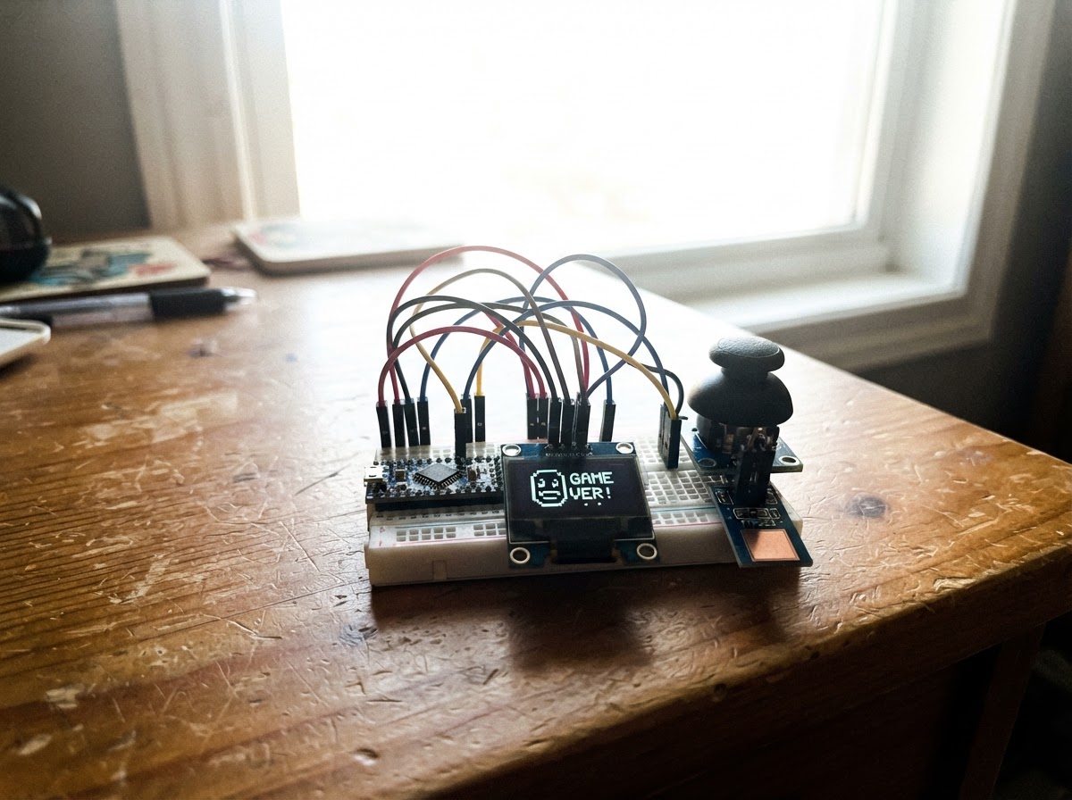
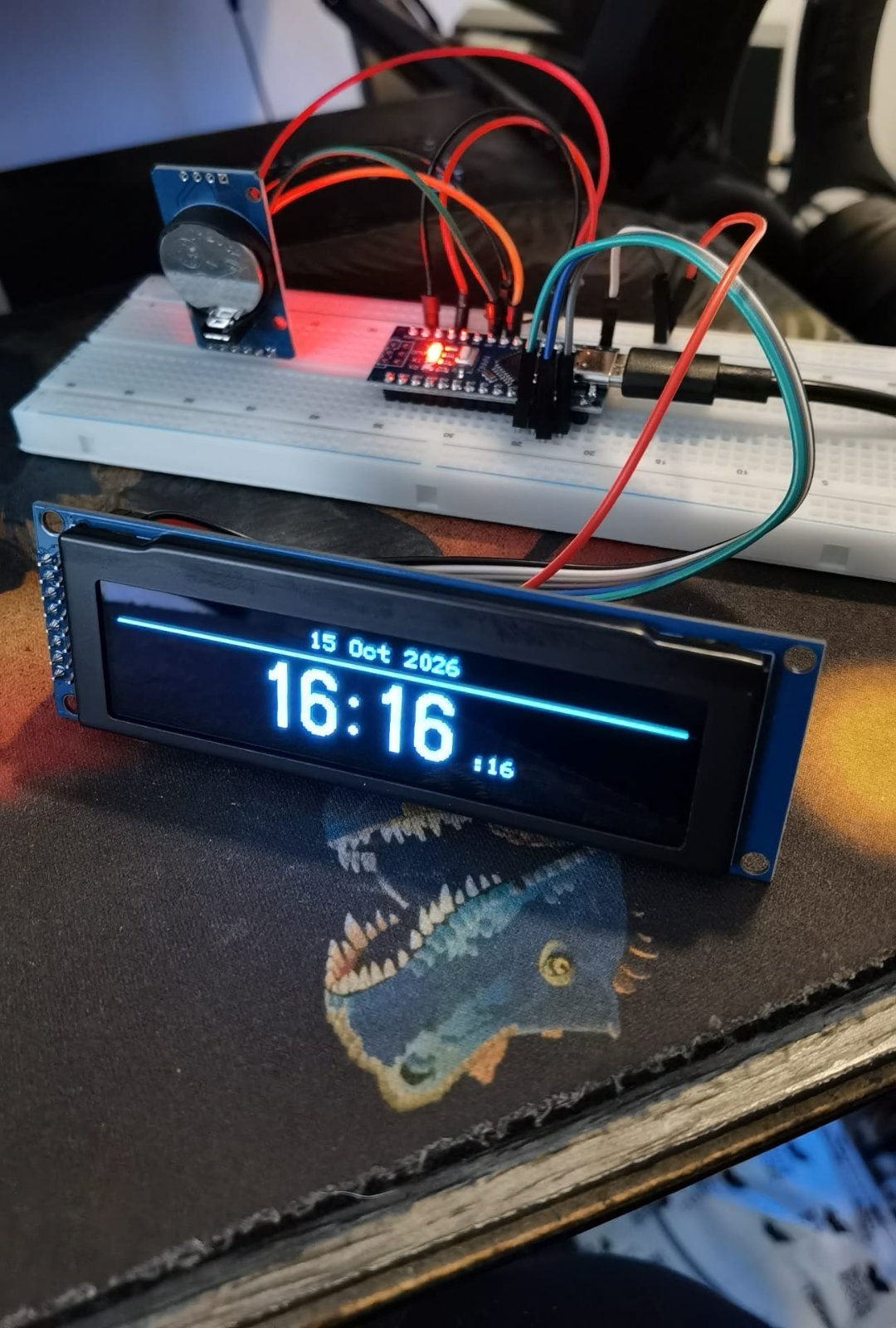
Interactive OLED Face Games brings a playful desk companion to life on a 128x64 OLED display. The project combines an Arduino Uno with a joystick module for directional control, a capacitive touch sensor for interaction, and animated face graphics that respond to player input. Readers will receive a complete wiring diagram, parts list, and step-by-step assembly instructions to build their own interactive display.
The firmware drives two interactive modes: a pet-simulation where touching the screen makes the face happy and animated, and a dodge-style game where the joystick controls a player character avoiding obstacles. This guide includes all necessary code, component specifications, and assembly steps to get the desk buddy running and responding to input within minutes.
Wiring diagram

Gather all the parts
Assemble it in 5 steps
1. Power off before wiring
Disconnect the Arduino Nano from USB before making connections. Place the Nano, OLED, joystick module, and TTP223 touch module on a breadboard or arrange them in the desk enclosure.
- Keep the OLED where it will be easy to see from your desk.
- Use short wires for the I2C OLED signals.
- Do not connect or move wires while the Nano is powered.
2. Wire the OLED display
Connect OLED VCC to the Nano 3.3V pin and OLED GND to Nano GND. Connect OLED SDA to Nano A4 and OLED SCL to Nano A5. This project expects the common 128×64 SSD1306 I2C OLED at address 0x3C.
- A4 is SDA and A5 is SCL on the Nano.
- Keep the VCC connection at 3.3V as specified for this OLED module.
- Check the labels on the OLED carefully: reversing VCC and GND can damage it.
3. Wire the joystick
Connect joystick VCC to Nano 5V and joystick GND to Nano GND. Connect VRx to A0, VRy to A1, and SW to digital pin D3.
- VRx is left/right movement and VRy makes the desk buddy look up or down.
- The SW pin is the button activated by pressing the joystick knob down.
- All modules must share the Nano GND connection.
4. Wire the touch pad
Connect the TTP223 VCC pin to Nano 3.3V, GND to Nano GND, and SIG to digital pin D2. Leave the module in its normal momentary-output configuration.
- Mount the touch pad where you can tap it as a 'pet' button.
- The touch pad increments the pet count and triggers a happy animation; while playing the game it returns to the buddy screen.
- Avoid touching the exposed sensor pad while checking your wiring, because it may trigger.
5. Power and use the desk buddy
Recheck every power and ground connection, then power the Nano through its USB port. The buddy idles, blinks, bobs, and follows joystick movement with its eyes. Tap the touch pad to pet it. Press the joystick button to start the Dodge game; move left/right with the joystick and touch the pad to exit.
- Use Schematik's Deploy button to compile and flash the finished firmware.
- If the OLED remains blank, first verify its SDA/A4 and SCL/A5 connections and its 3.3V power connection.
- Use only the Nano USB connection for this build; do not connect a separate supply at the same time.
Review all connections
1. Connections between "oled_1" and "Arduino"
2. Connections between "joystick_1" and "Arduino"
3. Connections between "touch_1" and "Arduino"
Deploy the firmware
#include <Arduino.h>
#include <Wire.h>
#include <Adafruit_GFX.h>
#include <Adafruit_SSD1306.h>

#define SCREEN_WIDTH 128
#define SCREEN_HEIGHT 64
#define OLED_RESET -1
#define OLED_ADDRESS 0x3C

#define JOY_X_PIN A0
#define JOY_Y_PIN A1
#define JOY_BUTTON_PIN 3
#define TOUCH_PIN 2


// Forward declarations
bool pressedEdge(uint8_t pin);
void drawFace();
void resetGame();
void drawGame();

Adafruit_SSD1306 display(SCREEN_WIDTH, SCREEN_HEIGHT, &Wire, OLED_RESET);

bool gameMode = false;
bool lastTouch = false;
unsigned long lastTouchMs = 0;
unsigned long gameLastStepMs = 0;
unsigned long happyUntilMs = 0;
uint16_t pets = 0;
uint16_t score = 0;
int playerX = 58;
int obstacleX = 20;
int obstacleY = -8;
int obstacleSpeed = 2;

bool pressedEdge(uint8_t pin) {
  static bool lastJoyButton = HIGH;
  bool now = digitalRead(pin);
  bool edge = (lastJoyButton == HIGH && now == LOW);
  lastJoyButton = now;
  return edge;
}

void drawFace() {
  int joyX = analogRead(JOY_X_PIN);
  int joyY = analogRead(JOY_Y_PIN);
  int lookX = map(joyX, 0, 1023, -5, 5);
  int lookY = map(joyY, 0, 1023, -3, 3);
  unsigned long now = millis();
  bool excited = now < happyUntilMs;
  bool blink = !excited && (now % 4200UL) < 140UL;
  int bob = sin((float)now / (excited ? 120.0 : 340.0)) * (excited ? 3 : 2);

  display.clearDisplay();
  display.setTextSize(1);
  display.setTextColor(SSD1306_WHITE);
  display.setCursor(2, 0);
  if (excited) display.print(F("YAY! thanks!"));
  else display.print(F("DESK BUDDY  pet me"));

  display.drawRoundRect(20, 7 + bob, 88, 53, 22, SSD1306_WHITE);
  display.drawRoundRect(23, 10 + bob, 82, 47, 19, SSD1306_WHITE);
  if (excited) {
    display.drawLine(27, 16 + bob, 17, 10 + bob, SSD1306_WHITE);
    display.drawLine(101, 16 + bob, 111, 10 + bob, SSD1306_WHITE);
  } else {
    display.drawLine(26, 16 + bob, 18, 20 + bob, SSD1306_WHITE);
    display.drawLine(102, 16 + bob, 110, 20 + bob, SSD1306_WHITE);
  }

  if (blink) {
    display.drawLine(37, 30 + bob, 57, 30 + bob, SSD1306_WHITE);
    display.drawLine(71, 30 + bob, 91, 30 + bob, SSD1306_WHITE);
  } else {
    display.drawCircle(47, 30 + bob, 10, SSD1306_WHITE);
    display.drawCircle(81, 30 + bob, 10, SSD1306_WHITE);
    display.fillCircle(47 + lookX, 30 + bob + lookY, 4, SSD1306_WHITE);
    display.fillCircle(81 + lookX, 30 + bob + lookY, 4, SSD1306_WHITE);
  }

  display.drawLine(64, 34 + bob, 61, 40 + bob, SSD1306_WHITE);
  display.drawLine(61, 40 + bob, 66, 40 + bob, SSD1306_WHITE);
  display.drawLine(48, 48 + bob, 54, 52 + bob, SSD1306_WHITE);
  display.drawLine(54, 52 + bob, 64, 53 + bob, SSD1306_WHITE);
  display.drawLine(64, 53 + bob, 74, 52 + bob, SSD1306_WHITE);
  display.drawLine(74, 52 + bob, 80, 48 + bob, SSD1306_WHITE);
  display.setCursor(2, 56);
  display.print(F("pets:"));
  display.print(pets);
  display.print(F("  touch: game"));
  display.display();
}

void resetGame() {
  playerX = 58;
  obstacleX = random(5, 113);
  obstacleY = -8;
  obstacleSpeed = 2;
  score = 0;
}

void drawGame() {
  int joyX = analogRead(JOY_X_PIN);
  if (joyX < 350 && playerX > 1) playerX -= 3;
  if (joyX > 670 && playerX < 115) playerX += 3;

  unsigned long now = millis();
  if (now - gameLastStepMs > 50) {
    gameLastStepMs = now;
    obstacleY += obstacleSpeed;
    if (obstacleY > 64) {
      obstacleY = -8;
      obstacleX = random(3, 116);
      score++;
      if (score % 5 == 0 && obstacleSpeed < 5) obstacleSpeed++;
    }
  }

  bool hit = obstacleY + 7 >= 54 && obstacleY <= 62 && obstacleX + 7 >= playerX && obstacleX <= playerX + 12;
  display.clearDisplay();
  display.setTextSize(1);
  display.setTextColor(SSD1306_WHITE);
  display.setCursor(0, 0);
  display.print(F("DODGE: "));
  display.print(score);
  display.drawLine(0, 63, 127, 63, SSD1306_WHITE);
  display.fillRect(playerX, 55, 13, 7, SSD1306_WHITE);
  display.drawRect(obstacleX, obstacleY, 8, 8, SSD1306_WHITE);

  if (hit) {
    display.fillRect(18, 21, 92, 20, SSD1306_BLACK);
    display.drawRect(18, 21, 92, 20, SSD1306_WHITE);
    display.setCursor(27, 26);
    display.print(F("GAME OVER"));
    display.setCursor(23, 33);
    display.print(F("press stick"));
    display.display();
    while (digitalRead(JOY_BUTTON_PIN) == HIGH) {
      if (digitalRead(TOUCH_PIN) == HIGH) return;
      delay(5);
    }
    resetGame();
    delay(200);
    return;
  }
  display.display();
}

void setup() {
  pinMode(JOY_BUTTON_PIN, INPUT_PULLUP);
  pinMode(TOUCH_PIN, INPUT);
  randomSeed(analogRead(A2));
  if (!display.begin(SSD1306_SWITCHCAPVCC, OLED_ADDRESS)) {
    for (;;) { }
  }
  display.clearDisplay();
  display.setTextColor(SSD1306_WHITE);
  display.setTextSize(1);
  display.setCursor(17, 25);
  display.print(F("FACE CONSOLE"));
  display.display();
  delay(900);
  resetGame();
}

void loop() {
  bool touchNow = digitalRead(TOUCH_PIN) == HIGH;
  if (touchNow && !lastTouch && millis() - lastTouchMs > 250) {
    lastTouchMs = millis();
    if (gameMode) {
      gameMode = false;
    } else {
      pets++;
      happyUntilMs = millis() + 1600UL;
    }
  }
  if (!gameMode && pressedEdge(JOY_BUTTON_PIN)) {
    gameMode = true;
    resetGame();
  }
  lastTouch = touchNow;

  if (gameMode) {
    drawGame();
  } else {
    drawFace();
  }
  delay(20);
}
Remix this project
Make it yours in one click
Open a full copy of this project in your own Schematik workspace — diagram, code, parts, and assembly steps included. Swap the sensor, add features, or redesign the whole thing with AI. The author's original stays untouched.