Community project
Intrusion Detection Alarm
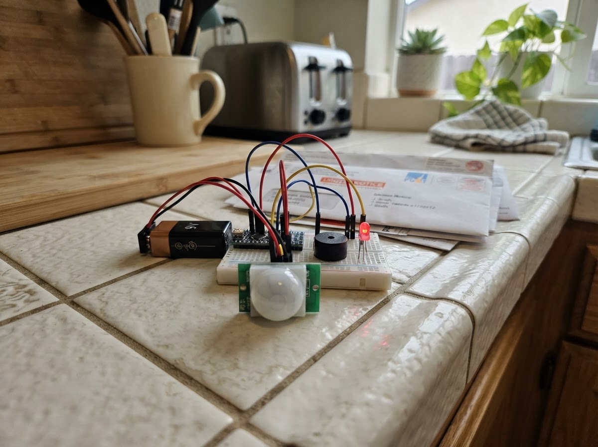
This intrusion detection alarm uses an ESP32 microcontroller paired with a PIR motion sensor to monitor a space and trigger an audible and visual alert when movement is detected. The system creates its own WiFi access point, allowing users to monitor status and silence the alarm remotely from any connected device.
This guide provides a complete parts list, wiring diagram, and step-by-step assembly instructions for connecting the HC-SR501 PIR sensor, buzzer, and LED indicator to the ESP32. The included firmware handles motion detection, alarm triggering with a 30-second duration, and a web interface for real-time status monitoring and remote alarm control.
Wiring diagram

Gather all the parts
Assemble it in 5 steps
1. Desconecta la alimentación y prepara la protoboard
Antes de cablear, desconecta el ESP32 del USB. Coloca el ESP32 atravesando la ranura central de la protoboard y reserva un carril para GND común.
- Usa cables cortos para las señales y conserva todos los GND conectados entre sí.
- No conectes ni retires cables mientras el ESP32 esté alimentado.
2. Conecta el sensor PIR HC-SR501
Conecta VCC del pir_1 al pin VIN/5V del ESP32, GND a GND y OUT a GPIO27. Dirige la lente hacia la zona vigilada. El módulo se estabiliza al encenderse, normalmente durante unos 60 segundos.
- Ajusta después los dos potenciómetros del PIR: sensibilidad y tiempo de salida, si es necesario.
- El ESP32 trabaja a lógica de 3.3 V: usa un HC-SR501 estándar, cuya salida OUT es apta para esta entrada. No conectes OUT a un pin de 5 V.
3. Conecta el buzzer de alarma
Conecta GND del buzzer_1 a GND y SIGNAL a GPIO25 del ESP32. Usa un buzzer activo de 3.3 V y baja corriente; si tu buzzer necesita 5 V o consume más de lo que un GPIO soporta, debe añadirse un transistor de control.
- Si el módulo tiene pines marcados + y -, conecta la entrada de señal al + o SIG según su serigrafía y el - a GND.
- No uses directamente un buzzer de alta potencia con un GPIO del ESP32.
4. Conecta el LED indicador con su resistencia
Conecta GPIO26 a una resistencia de 220 ohmios; conecta el otro extremo de la resistencia al ánodo (pata larga) del led_1. Conecta el cátodo (pata corta o lado plano) a GND.
- La resistencia puede ir antes o después del LED, siempre en serie.
- No conectes el LED directamente al GPIO: la resistencia de 220 ohmios es obligatoria para limitar la corriente.
5. Revisa y alimenta
Comprueba que PIR, buzzer y LED comparten GND con el ESP32. Alimenta el ESP32 por su puerto USB. Tras la estabilización del PIR, al detectar un nuevo movimiento se encenderán el LED y buzzer durante 30 segundos; también se puede silenciar desde la página local.
- Conecta el teléfono a la red Wi‑Fi Alarma-ESP32, clave seguridad, y abre la dirección IP indicada por el monitor serie (normalmente http://192.168.4.1).
- La red Wi‑Fi local permite consultar y silenciar el sistema cerca del ESP32; no es una notificación por Internet ni sustituye un sistema de seguridad certificado.
Review all connections
1. Connections between "pir_1" and "ESP32"
2. Connections between "buzzer_1" and "ESP32"
3. Connections between "led_1" and "ESP32"
Deploy the firmware
#include <Arduino.h>
#include <WiFi.h>
#include <WebServer.h>


// Forward declarations
String pageHtml();
void handleRoot();
void handleSilence();
void startAlarm();

constexpr int PIR_PIN = 27;
constexpr int BUZZER_PIN = 25;
constexpr int LED_PIN = 26;

const char *AP_SSID = "Alarma-ESP32";
const char *AP_PASSWORD = "seguridad";
WebServer server(80);

bool alarmActive = false;
bool lastPirState = false;
unsigned long alarmStartedAt = 0;
unsigned long lastStatusPrintAt = 0;
const unsigned long ALARM_DURATION_MS = 30000;

String pageHtml() {
  String state = alarmActive ? "<strong style='color:#d11'>ALARMA ACTIVA</strong>" : "<strong style='color:#187a2f'>Sistema vigilando</strong>";
  String motion = digitalRead(PIR_PIN) ? "Movimiento detectado" : "Sin movimiento";
  return String("<!doctype html><html><head><meta name='viewport' content='width=device-width,initial-scale=1'>") +
         "<meta http-equiv='refresh' content='3'><title>Alarma ESP32</title></head>" +
         "<body style='font-family:Arial;max-width:500px;margin:30px auto;padding:16px'>" +
         "<h1>Alarma ESP32</h1><p>Estado: " + state + "</p><p>Sensor PIR: " + motion + "</p>" +
         "<p>Red local: " + WiFi.softAPIP().toString() + "</p>" +
         "<p><a href='/silenciar'><button style='padding:12px'>Silenciar alarma</button></a></p>" +
         "</body></html>";
}

void handleRoot() {
  server.send(200, "text/html; charset=utf-8", pageHtml());
}

void handleSilence() {
  alarmActive = false;
  digitalWrite(LED_PIN, LOW);
  digitalWrite(BUZZER_PIN, LOW);
  Serial.println("Alarma silenciada desde la pagina web.");
  server.sendHeader("Location", "/");
  server.send(303);
}

void startAlarm() {
  alarmActive = true;
  alarmStartedAt = millis();
  digitalWrite(LED_PIN, HIGH);
  digitalWrite(BUZZER_PIN, HIGH);
  Serial.println("ALERTA: movimiento no autorizado detectado.");
}

void setup() {
  Serial.begin(115200);
  pinMode(PIR_PIN, INPUT);
  pinMode(BUZZER_PIN, OUTPUT);
  pinMode(LED_PIN, OUTPUT);
  digitalWrite(BUZZER_PIN, LOW);
  digitalWrite(LED_PIN, LOW);

  WiFi.mode(WIFI_AP);
  WiFi.softAP(AP_SSID, AP_PASSWORD);
  Serial.print("Red WiFi creada: ");
  Serial.println(AP_SSID);
  Serial.print("Abrir en el navegador: http://");
  Serial.println(WiFi.softAPIP());

  server.on("/", handleRoot);
  server.on("/silenciar", handleSilence);
  server.begin();
  Serial.println("Espere aproximadamente 60 segundos para que el PIR se estabilice.");
}

void loop() {
  server.handleClient();
  bool pirState = digitalRead(PIR_PIN) == HIGH;
  if (pirState && !lastPirState && !alarmActive) {
    startAlarm();
  }
  lastPirState = pirState;

  if (alarmActive && millis() - alarmStartedAt >= ALARM_DURATION_MS) {
    alarmActive = false;
    digitalWrite(LED_PIN, LOW);
    digitalWrite(BUZZER_PIN, LOW);
    Serial.println("Alarma finalizada automaticamente tras 30 segundos.");
  }

  if (millis() - lastStatusPrintAt >= 5000) {
    lastStatusPrintAt = millis();
    Serial.print("PIR=");
    Serial.print(pirState ? "MOVIMIENTO" : "sin movimiento");
    Serial.print(", alarma=");
    Serial.println(alarmActive ? "ACTIVA" : "vigilando");
  }
}
Remix this project
Make it yours in one click
Open a full copy of this project in your own Schematik workspace — diagram, code, parts, and assembly steps included. Swap the sensor, add features, or redesign the whole thing with AI. The author's original stays untouched.
Related projects

Create A Complete Electrical Schematic Esp32 Sma
ESP32 · September 17, 2026Ayansh Agrawal
ESP32 Kare Ekran Projeleri
ESP32 · September 16, 2026Seref Ai
Component Qty --------------------------- ------
ESP32 · September 16, 2026Yathartha Chakrawal