Community project
Make This
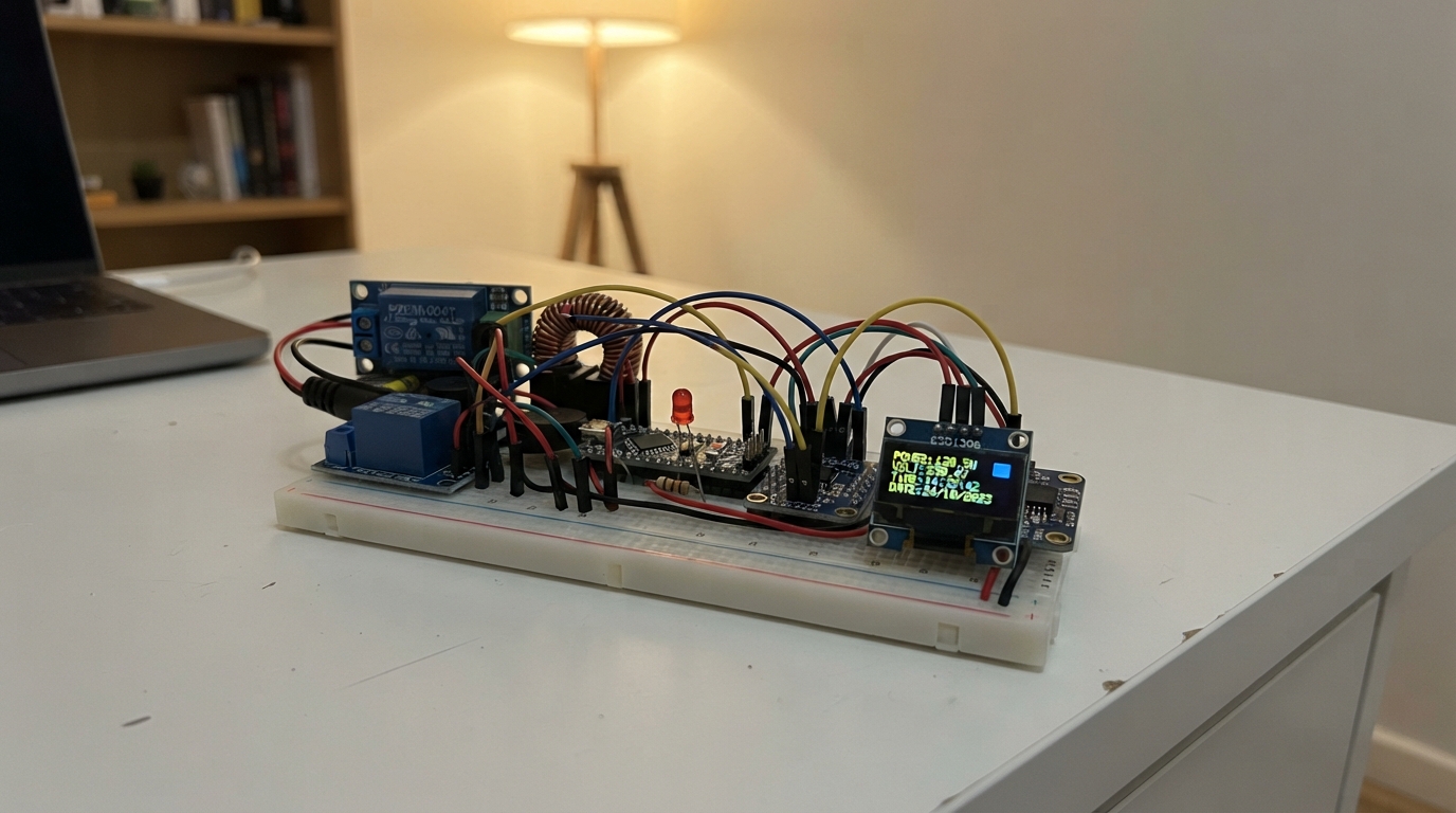
This project builds a smart outlet monitor that tracks real-time power consumption and automatically cuts power when usage exceeds a threshold. The ESP32 reads voltage, current, power, and energy from a PZEM-004T meter, displays readings on an OLED screen with precise timekeeping from an RTC module, and controls a relay to disconnect the load when needed. Status LEDs and a buzzer provide visual and audio feedback.
The guide includes a complete wiring diagram showing how to safely integrate the high-voltage mains path with the low-voltage control circuit using opto-isolation, a full parts list with sourcing notes, Arduino firmware with web server capability for remote monitoring, and step-by-step assembly instructions that keep dangerous voltages isolated during construction and testing.
Wiring diagram

Gather all the parts
Assemble it in 8 steps
1. Keep the high-voltage section separate
Use a flame-retardant closed electrical enclosure with cable glands, a strain relief for mains_cord_1, and a covered panel outlet_1. Have a qualified electrician install the mains cord, mcb_1, acdc_supply_1, relay_1 switching terminals, PZEM-004T mains terminals, outlet, and the current clamp. Nothing carrying mains voltage may be placed on a breadboard or left exposed.
- Put the low-voltage ESP32 compartment behind a solid insulating barrier from the mains terminals.
- Use parts rated for your local mains voltage, load current, and enclosure temperature.
- Touching or miswiring live mains conductors can cause fatal electric shock or fire; turn power off at the supply and use a qualified electrician for this step.
2. Install the mains outlet path
Inside the closed enclosure, the electrician connects the plug lead live and neutral to the matching two-pole breaker inputs. The protected live output goes to relay_1 COM and relay_1 NO goes to outlet_1 L; the protected neutral goes to outlet_1 N. Protective earth goes directly from the incoming earth conductor to outlet_1 PE and is never joined to ESP32 GND.
- NO means the outlet is off until the relay is deliberately turned on.
- Use correctly sized terminals and insulated crimp ferrules rather than loose twisted wire.
- Do not connect protective earth to the low-voltage ground rail — doing so defeats the safety separation designed into the power supply.
3. Fit the power meter safely
The electrician powers pzem_1 from the protected mains side as required by its own terminal markings, then clips its split current sensor around only the single live conductor feeding outlet_1. Do not pass neutral or both conductors through the clamp. On the low-voltage connector, connect PZEM VCC to 5V (power) and PZEM GND to GND (ground).
- A clamp around both live and neutral reads near zero because their magnetic fields cancel.
- Keep the PZEM terminal cover fitted after testing.
- The PZEM mains terminals are hazardous even though its serial connector is low voltage; never handle its terminals while plugged in.
4. Wire the protected serial link
Connect level_shifter_1 HV to 5V (power), LV to 3V3 (power), and GND to GND (ground). Connect PZEM TX to shifter HV1 (meter data out), shifter LV1 to GPIO16 (ESP32 receive data), GPIO17 to shifter LV2 (ESP32 send data), and shifter HV2 to PZEM RX. This level shifter stops the meter's 5V signal from reaching the ESP32's 3.3V input directly.
- Keep these four serial wires short and routed away from the mains wiring.
- The TX and RX names cross: one device talks into the other device's receive connection.
- Do not connect the PZEM TX pin directly to GPIO16 — the 5V signal can damage the ESP32.
5. Wire the display and clock
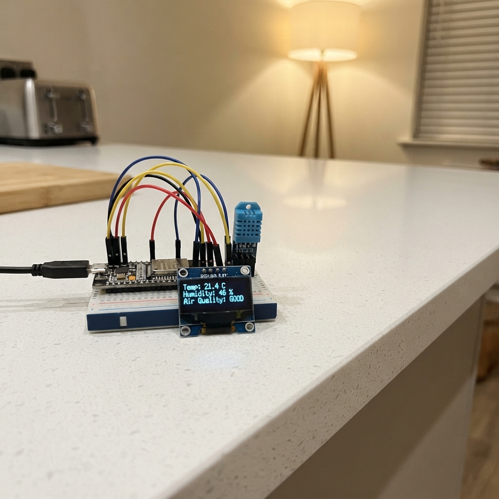
Connect oled_1 VCC to 3V3 (power), GND to GND (ground), SDA to GPIO21 (data), and SCL to GPIO22 (clock). Connect rtc_1 VIN to 3V3 (power), GND to GND (ground), SDA to GPIO21 (data), and SCL to GPIO22 (clock). Both small boards share the same two data wires.
- The OLED and clock can share SDA and SCL because each responds to a different built-in address.
- Fit a backup coin cell to the clock module if you want it to retain the time when the controller is unplugged.
- Make sure VCC and GND are not swapped — swapped power can damage the display or clock module.
6. Wire the relay control and alarm
Connect relay_1 VCC to 5V (power), relay_1 GND to GND (ground), and relay_1 IN to GPIO25 (control). Connect buzzer_1 SIGNAL to GPIO26 (alarm signal) and its other pin to GND (ground). The relay module must be the 5V-coil type that accepts a 3.3V ESP32 control signal.
- The firmware starts with the relay off and only enables it after a valid meter reading.
- Mount the buzzer in the low-voltage side of the enclosure so its sound can escape through a small protected opening.
- Do not use an unknown relay module that needs a 5V control signal; that can overload the ESP32 GPIO pin.
7. Add the three status lights
For each LED, connect its short leg to GND (ground). Connect GPIO27 to res_green_1 P1, res_green_1 P2 to the green LED long leg; GPIO32 to res_yellow_1 P1, res_yellow_1 P2 to the yellow LED long leg; and GPIO33 to res_red_1 P1, res_red_1 P2 to the red LED long leg. Each 220 Ω resistor limits current so the LED and ESP32 are protected.
- The long LED leg is positive; if one stays dark, turn power off and reverse that LED.
- Green means normal, yellow means outlet held off, and red plus buzzer means an alarm or lost meter reading.
- Never connect an LED straight to a GPIO pin without its 220 Ω resistor — too much current can damage the LED or ESP32.
8. Power and test the low-voltage side first
Before the electrician connects mains power, plug the ESP32 into USB and verify the OLED and status lights. Once the mains enclosure has been closed and inspected, apply mains power. Join the ESP32 Wi-Fi network named Smart-Outlet-Monitor with password outlet2026, then open 192.168.4.1 on your phone to see readings.
- Use a small load first, such as a table lamp, and confirm its measured power is comfortably below the 1500 W safety limit.
- The 1500 W limit can be changed in the firmware later if your electrician confirms the wiring, outlet, relay, and breaker ratings support a different limit.
- Close and secure the enclosure before applying mains power; exposed terminals can cause fatal electric shock.
Review all connections
1. Connections between "pzem_1" and "ESP32"
2. Connections between "level_shifter_1" and "ESP32"
3. Connections between "rtc_1" and "ESP32"
4. Connections between "oled_1" and "ESP32"
5. Connections between "relay_1" and "ESP32"
6. Connections between "buzzer_1" and "ESP32"
7. Connections between "res_green_1" and "ESP32"
8. Connections between "led_green_1" and "ESP32"
9. Connections between "res_yellow_1" and "ESP32"
10. Connections between "led_yellow_1" and "ESP32"
11. Connections between "res_red_1" and "ESP32"
12. Connections between "led_red_1" and "ESP32"
13. Connections between "mains_cord_1" and "ESP32"
14. Connections between "mcb_1" and "ESP32"
15. Connections between "acdc_supply_1" and "ESP32"
Deploy the firmware
#include <Arduino.h>
#include <Wire.h>
#include <WiFi.h>
#include <WebServer.h>
#include <PZEM004Tv30.h>
#include <RTClib.h>
#include <Adafruit_GFX.h>
#include <Adafruit_SSD1306.h>
#include <math.h>


// Forward declarations
String timestampNow();
void setRelay(bool on);
void setIndicators();
void drawDisplay();
String valueOrDash(float value, uint8_t decimals);
void handleRoot();
void sampleMeter();

constexpr int PZEM_RX_PIN = 16;
constexpr int PZEM_TX_PIN = 17;
constexpr int I2C_SDA_PIN = 21;
constexpr int I2C_SCL_PIN = 22;
constexpr int RELAY_PIN = 25;
constexpr int BUZZER_PIN = 26;
constexpr int GREEN_LED_PIN = 27;
constexpr int YELLOW_LED_PIN = 32;
constexpr int RED_LED_PIN = 33;

constexpr uint32_t SAMPLE_INTERVAL_MS = 2000;
constexpr float POWER_LIMIT_W = 1500.0f;
constexpr float CLEAR_LIMIT_W = 1400.0f;
constexpr bool RELAY_ON_LEVEL = LOW;  // Common opto-isolated relay modules are active-low.
constexpr char AP_SSID[] = "Smart-Outlet-Monitor";
constexpr char AP_PASSWORD[] = "outlet2026";

PZEM004Tv30 pzem(Serial2, PZEM_RX_PIN, PZEM_TX_PIN);
RTC_DS3231 rtc;
Adafruit_SSD1306 display(128, 64, &Wire, -1);
WebServer server(80);

float voltageV = NAN;
float currentA = NAN;
float powerW = NAN;
float energyKwh = NAN;
bool meterOnline = false;
bool alarmLatched = false;
bool relayEnabled = false;
String lastAlarmTime = "None";
String lastStatus = "Starting";
uint32_t lastSampleMs = 0;

String timestampNow() {
  DateTime now = rtc.now();
  char text[24];
  snprintf(text, sizeof(text), "%04d-%02d-%02d %02d:%02d:%02d",
           now.year(), now.month(), now.day(), now.hour(), now.minute(), now.second());
  return String(text);
}

void setRelay(bool on) {
  relayEnabled = on;
  digitalWrite(RELAY_PIN, on ? RELAY_ON_LEVEL : !RELAY_ON_LEVEL);
}

void setIndicators() {
  digitalWrite(GREEN_LED_PIN, meterOnline && relayEnabled && !alarmLatched ? HIGH : LOW);
  digitalWrite(YELLOW_LED_PIN, meterOnline && !relayEnabled && !alarmLatched ? HIGH : LOW);
  digitalWrite(RED_LED_PIN, alarmLatched || !meterOnline ? HIGH : LOW);
  digitalWrite(BUZZER_PIN, alarmLatched || !meterOnline ? HIGH : LOW);
}

void drawDisplay() {
  static String lastDrawn;
  String visibleState = String(meterOnline) + "|" + String(alarmLatched) + "|" + lastStatus + "|" +
                        valueOrDash(voltageV, 1) + "|" + valueOrDash(currentA, 2) + "|" +
                        valueOrDash(powerW, 0) + "|" + valueOrDash(energyKwh, 3);
  if (visibleState == lastDrawn) return;
  lastDrawn = visibleState;

  display.clearDisplay();
  display.setTextColor(SSD1306_WHITE);
  display.setTextSize(1);
  display.setCursor(0, 0);
  display.println("SMART OUTLET");
  display.drawLine(0, 10, 127, 10, SSD1306_WHITE);

  if (!meterOnline) {
    display.setCursor(0, 18);
    display.println("Meter not responding");
    display.println("Outlet switched OFF");
  } else {
    char line[28];
    snprintf(line, sizeof(line), "V: %5.1f V", voltageV);
    display.setCursor(0, 15); display.println(line);
    snprintf(line, sizeof(line), "I: %5.2f A", currentA);
    display.setCursor(0, 27); display.println(line);
    snprintf(line, sizeof(line), "P: %5.0f W", powerW);
    display.setCursor(0, 39); display.println(line);
    snprintf(line, sizeof(line), "E: %5.3f kWh", energyKwh);
    display.setCursor(0, 51); display.println(line);
  }

  if (alarmLatched) {
    display.fillRect(92, 0, 36, 9, SSD1306_WHITE);
    display.setTextColor(SSD1306_BLACK);
    display.setCursor(95, 1);
    display.print("ALARM");
    display.setTextColor(SSD1306_WHITE);
  }
  display.display();
}

String valueOrDash(float value, uint8_t decimals) {
  return isnan(value) ? "--" : String(value, decimals);
}

void handleRoot() {
  String page = F("<!doctype html><html><head><meta name='viewport' content='width=device-width,initial-scale=1'>"
                  "<meta http-equiv='refresh' content='3'><style>body{font-family:Arial;background:#102235;color:#fff;margin:24px}"
                  ".card{background:#1d3852;border-radius:12px;padding:18px;max-width:430px}h1{font-size:1.4em}.ok{color:#65e572}.warn{color:#ffd166}.alarm{color:#ff6b6b}</style></head><body><div class='card'>"
                  "<h1>Smart Outlet Monitor</h1>");
  String css = alarmLatched || !meterOnline ? "alarm" : (relayEnabled ? "ok" : "warn");
  page += "<p class='" + css + "'><b>" + lastStatus + "</b></p>";
  page += "<p>Voltage: " + valueOrDash(voltageV, 1) + " V<br>";
  page += "Current: " + valueOrDash(currentA, 2) + " A<br>";
  page += "Power: " + valueOrDash(powerW, 0) + " W<br>";
  page += "Energy: " + valueOrDash(energyKwh, 3) + " kWh</p>";
  page += "<p>Safety limit: " + String(POWER_LIMIT_W, 0) + " W<br>Last alarm: " + lastAlarmTime + "</p>";
  page += "<p>Connect to <b>" + String(AP_SSID) + "</b>, then open <b>192.168.4.1</b>.</p>";
  page += F("</div></body></html>");
  server.send(200, "text/html", page);
}

void sampleMeter() {
  float newVoltage = pzem.voltage();
  float newCurrent = pzem.current();
  float newPower = pzem.power();
  float newEnergy = pzem.energy();

  meterOnline = !isnan(newVoltage) && !isnan(newCurrent) && !isnan(newPower) && !isnan(newEnergy);
  if (!meterOnline) {
    setRelay(false);
    alarmLatched = true;
    if (lastAlarmTime == "None") lastAlarmTime = timestampNow();
    lastStatus = "Meter fault - outlet OFF";
  } else {
    voltageV = newVoltage;
    currentA = newCurrent;
    powerW = newPower;
    energyKwh = newEnergy;
    if (powerW > POWER_LIMIT_W) {
      if (!alarmLatched) lastAlarmTime = timestampNow();
      alarmLatched = true;
      setRelay(false);
      lastStatus = "Overload alarm - outlet OFF";
    } else if (alarmLatched && powerW < CLEAR_LIMIT_W) {
      alarmLatched = false;
      setRelay(true);
      lastStatus = "Load normal - outlet ON";
    } else if (!alarmLatched) {
      setRelay(true);
      lastStatus = "Load normal - outlet ON";
    }
  }
  setIndicators();
  drawDisplay();
  Serial.printf("%s | %s | %.1f V, %.2f A, %.0f W, %.3f kWh\n", timestampNow().c_str(), lastStatus.c_str(), voltageV, currentA, powerW, energyKwh);
}

void setup() {
  Serial.begin(115200);
  pinMode(RELAY_PIN, OUTPUT);
  pinMode(BUZZER_PIN, OUTPUT);
  pinMode(GREEN_LED_PIN, OUTPUT);
  pinMode(YELLOW_LED_PIN, OUTPUT);
  pinMode(RED_LED_PIN, OUTPUT);
  setRelay(false); // Fail safe: outlet remains off until the first valid meter reading.
  digitalWrite(BUZZER_PIN, LOW);

  Wire.begin(I2C_SDA_PIN, I2C_SCL_PIN);
  rtc.begin();
  if (rtc.lostPower()) rtc.adjust(DateTime(F(__DATE__), F(__TIME__)));

  if (!display.begin(SSD1306_SWITCHCAPVCC, 0x3C)) {
    Serial.println("OLED allocation failed");
  }
  drawDisplay();

  WiFi.mode(WIFI_AP);
  WiFi.softAP(AP_SSID, AP_PASSWORD);
  server.on("/", handleRoot);
  server.begin();
  Serial.print("Monitoring page: http://");
  Serial.println(WiFi.softAPIP());
}

void loop() {
  server.handleClient();
  if (millis() - lastSampleMs >= SAMPLE_INTERVAL_MS) {
    lastSampleMs = millis();
    sampleMeter();
  }
}
Remix this project
Make it yours in one click
Open a full copy of this project in your own Schematik workspace — diagram, code, parts, and assembly steps included. Swap the sensor, add features, or redesign the whole thing with AI. The author's original stays untouched.