Community project
Motorized Curd Churner
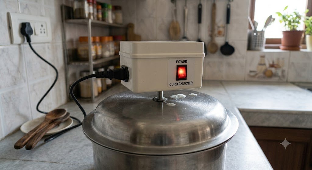
The Motorized Curd Churner automates the traditional process of churning curd into butter or paneer using a 12 V gear motor controlled by an Arduino and an IBT-2 H-bridge driver. The system features soft-start ramping, bidirectional control, and mechanical safeguards built into a compact ABS enclosure with a removable shaft and handle assembly.
This guide provides a complete wiring diagram, parts list, and step-by-step assembly instructions for building a reliable churner from the ground up. Included is the Arduino firmware that manages motor acceleration, deceleration, and direction changes with conservative timing profiles to protect the mechanical drive train during operation.
Wiring diagram

Gather all the parts
Assemble it in 8 steps
1. Prepare the combined enclosure and layout
Use an ABS enclosure approximately 280 × 220 × 180 mm externally; do not go below about 250 × 200 × 160 mm until the actual motor length and bracket footprint are checked. The shaft exits through the center of the enclosure bottom. Plan a rigid horizontal 3 mm aluminum support plate inside the lower half, with the motor vertically above and the F626ZZ bearing directly below on one centerline. Keep a clear service path to the flexible-coupling grub screw.
- A 120 × 120 mm support plate is a starting point; enlarge it to suit the bracket.
- Keep at least 20 mm clearance around the motor, BTS7960 heatsink, and cable-routing paths.
- Place the DC socket, fuse, and rocker where they are reachable from outside.
- The enclosure is not food-contact equipment; mount it above the drip disc and away from washing/splash paths.
- Do not use the vessel lid as a structural support.
2. Install the motor plate, motor, and bearing
Bolt the 37–38 mm gear motor vertically to the rigid support plate. Seat the F626ZZ flanged bearing in the plate directly below the motor so its bore is exactly concentric with the motor shaft. Secure the plate to the ABS enclosure using through-bolts, large washers, and locknuts or metal threaded inserts.
- Check the motor shaft, coupling location, bearing bore, and bottom shaft exit using a straight 6 mm rod before final tightening.
- Use 3 mm aluminum rather than unsupported acrylic if possible.
- Leave room above the motor for its wires and below the plate for the bearing flange.
- The enclosure plastic alone must not carry motor torque or the shaft load.
- Misalignment causes coupling wear, bearing binding, and gearbox side load.
3. Build the removable shaft and handle assembly
With the adapter unplugged, fit the 6-to-6 mm flexible coupling between the motor shaft and the 6 mm stainless rod. Pass the rod through the F626ZZ bearing and tighten a 6 mm shaft collar immediately above the bearing to prevent the rod moving downward. Drill the wooden handle 6 mm diameter and 40 mm deep, roughen the rod end, epoxy it in, and add a small cross-pin after the epoxy is fully cured. Fit the 50–70 mm drip disc below the enclosure.
- Deburr the rod and tighten coupling screws onto a flat or small dimple where possible.
- Turn the shaft by hand; it must run freely with no wobble or rubbing.
- Arrange the coupling so its grub screw can be reached after opening the enclosure lid.
- Fit a fixed guard over the coupling before normal use; it is an entanglement and pinch hazard.
- Disconnect power before removing the shaft for cleaning.
4. Fit the vessel lid
Drill an 8–10 mm clearance hole in the separate removable vessel lid for the 6 mm rod. Position the enclosure so the drip disc overlaps the lid hole while remaining clear of it, and the handle/shaft turns without touching the lid.
- The lid hole is only a clearance/splash opening; allow free motion.
- Use food-safe materials and finishes for every part that can contact curd or splash.
- The bearing in the support plate—not the lid—must support and align the rotating shaft.
5. Install the power-entry and fused switch hardware
With the 12 V adapter unplugged, mount the 5.5 × 2.1 mm DC socket and KCD2 rocker switch in separate side/front-wall positions. Install the 5 A blade fuse in its 18 AWG-rated inline holder immediately after the socket positive terminal, where it can be serviced after opening the enclosure.
- Mark the socket as center-positive and identify the rocker OFF position.
- The holder may be rated 15 A; the installed 5 A fuse is the protection rating.
- Use grommets and strain relief at every wire exit.
- Never fit a fuse above 5 A merely to prevent a trip.
- Keep exposed 12 V terminals insulated.
6. Wire the switched 12 V motor-power circuit
Use 18 AWG stranded wire: DC socket + to fuse IN; fuse OUT to rocker IN+; DC socket − to rocker IN−. Split rocker OUT+ to BTS7960 B+ and Nano VIN. Split rocker OUT− to BTS7960 B− and Nano GND. Wire BTS7960 M+ and M− to the gear motor with 18 AWG wire.
- Keep power wiring around the enclosure perimeter and motor wiring away from the Nano signal wires.
- If rotation is opposite the desired initial direction, disconnect power and swap M+ and M−.
- Before connecting the Nano, verify with a meter that switched output is about 12 V and becomes 0 V when off.
- Never bypass the fuse.
- Switched 12 V goes only to BTS7960 B+ and Nano VIN—never to Nano 5 V or BTS7960 VCC.
7. Wire and mount the 5 V control electronics
Mount the Nano and BTS7960 on insulated standoffs, with the BTS7960 heatsink facing a clear air space. Connect Nano 5V to BTS7960 VCC, R_EN, and L_EN. Connect Nano GND to BTS7960 GND, Nano D9 to RPWM, and Nano D10 to LPWM. Leave R_IS and L_IS unconnected.
- Keep the Nano at least 20–30 mm from the driver power terminals and motor wiring.
- Route D9/D10 as a separate small signal bundle.
- Vent only in a splash-protected location if the driver becomes warm in use.
- Never apply 12 V to BTS7960 VCC, enable/PWM pins, or Nano 5V.
- Confirm the actual BTS7960/IBT-2 board uses separate 5 V VCC logic and 12 V B+/B− motor supply terminals.
8. Close, guard, and test
Secure terminal screws, cable restraints, the shaft collar, bearing mount, coupling screws, and enclosure lid. Install the coupling guard. Flash the existing bidirectional ramp firmware with Schematik’s Deploy button, then test first with an empty vessel and finally at low curd load.
- The existing firmware ramps each direction up and down gently and pauses before reversing.
- Stop and increase ramp time if thick curd produces jerking or audible strain.
- Check that the fuse holder, wires, driver, and motor remain only moderately warm.
- Never reach into the vessel or touch the shaft/coupling while powered.
- Stop immediately for binding, excess heat, adapter shutdown, unusual noise, or a fuse trip.
Review all connections
1. Connections between "adapter_12v" and "Arduino"
2. Connections between "dc_socket" and "Arduino"
3. Connections between "fuse_5a" and "Arduino"
4. Connections between "rocker_switch" and "Arduino"
5. Connections between "bts7960" and "Arduino"
Deploy the firmware
#include <Arduino.h>

// Arduino Nano + BTS7960 / IBT-2 madhani controller.
// RPWM and LPWM are mutually exclusive: only one is ever PWM-driven at a time.

// Forward declarations
void stopMotor();
void setMotorPwm(uint8_t activePin, uint8_t inactivePin, uint8_t pwm);
void rampUp(uint8_t activePin, uint8_t inactivePin);
void rampDown(uint8_t activePin, uint8_t inactivePin);
void runDirection(uint8_t activePin, uint8_t inactivePin);

constexpr uint8_t RPWM_PIN = 9;
constexpr uint8_t LPWM_PIN = 10;

// 60% of the Nano's 0..255 PWM range. This controls average motor voltage,
// not an exact 60% of unloaded RPM when the churner is under load.
constexpr uint8_t TARGET_PWM = 153;

// A conservative mechanical profile for the motor, coupling, shaft, and handle.
constexpr unsigned long RAMP_TIME_MS = 3000UL;
constexpr unsigned long STOP_TIME_MS = 1000UL;
constexpr unsigned long DIRECTION_DEAD_TIME_MS = 250UL;
constexpr uint8_t PWM_STEP = 3;

void stopMotor() {
  analogWrite(RPWM_PIN, 0);
  analogWrite(LPWM_PIN, 0);
  digitalWrite(RPWM_PIN, LOW);
  digitalWrite(LPWM_PIN, LOW);
}

void setMotorPwm(uint8_t activePin, uint8_t inactivePin, uint8_t pwm) {
  // Never command both sides of the H-bridge at once.
  analogWrite(inactivePin, 0);
  digitalWrite(inactivePin, LOW);
  analogWrite(activePin, pwm);
}

void rampUp(uint8_t activePin, uint8_t inactivePin) {
  const uint16_t steps = (TARGET_PWM + PWM_STEP - 1) / PWM_STEP;
  const unsigned long stepDelayMs = RAMP_TIME_MS / steps;

  for (uint16_t pwm = 0; pwm < TARGET_PWM; pwm += PWM_STEP) {
    setMotorPwm(activePin, inactivePin, static_cast<uint8_t>(pwm));
    delay(stepDelayMs);
  }
  setMotorPwm(activePin, inactivePin, TARGET_PWM);
}

void rampDown(uint8_t activePin, uint8_t inactivePin) {
  const uint16_t steps = (TARGET_PWM + PWM_STEP - 1) / PWM_STEP;
  const unsigned long stepDelayMs = RAMP_TIME_MS / steps;

  for (int16_t pwm = TARGET_PWM; pwm > 0; pwm -= PWM_STEP) {
    setMotorPwm(activePin, inactivePin, static_cast<uint8_t>(pwm));
    delay(stepDelayMs);
  }
  stopMotor();
}

void runDirection(uint8_t activePin, uint8_t inactivePin) {
  rampUp(activePin, inactivePin);
  rampDown(activePin, inactivePin);
  delay(STOP_TIME_MS);

  // Both bridge PWM inputs remain LOW before the next direction is selected.
  stopMotor();
  delay(DIRECTION_DEAD_TIME_MS);
}

void setup() {
  pinMode(RPWM_PIN, OUTPUT);
  pinMode(LPWM_PIN, OUTPUT);
  stopMotor();
  delay(DIRECTION_DEAD_TIME_MS);
}

void loop() {
  runDirection(RPWM_PIN, LPWM_PIN);  // Forward cycle.
  runDirection(LPWM_PIN, RPWM_PIN);  // Reverse cycle.
}
Remix this project
Make it yours in one click
Open a full copy of this project in your own Schematik workspace — diagram, code, parts, and assembly steps included. Swap the sensor, add features, or redesign the whole thing with AI. The author's original stays untouched.