Community project
Outdoor Air Quality Monitor
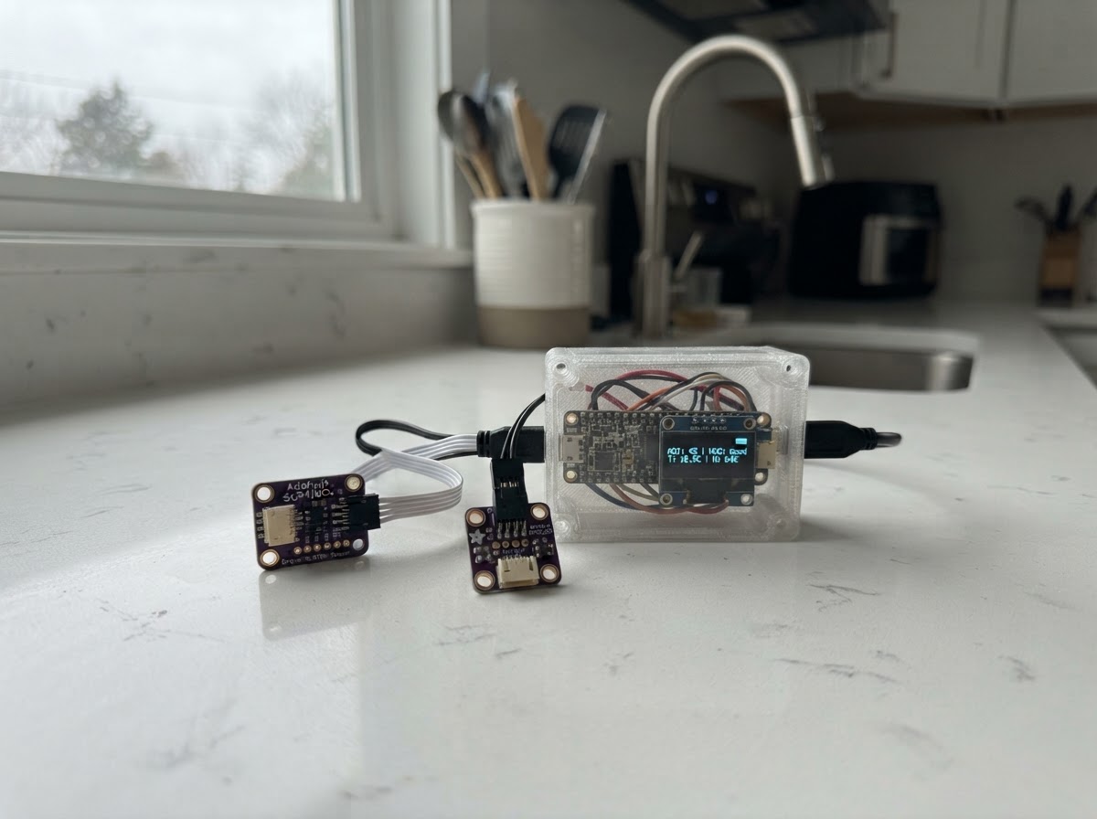
This outdoor air quality monitor uses an ESP32 to track volatile organic compounds (VOCs), nitrogen oxides (NOx), temperature, humidity, and atmospheric pressure. The SGP41 gas sensor provides real-time air quality readings while the BME280 captures environmental conditions, all connected via I2C for reliable data collection in outdoor settings.
This guide includes a complete parts list, wiring diagram showing sensor connections to the ESP32, step-by-step assembly instructions for the weatherproof enclosure, and ready-to-use firmware that initializes both sensors and begins logging air quality data. The monitor outputs readings via serial, making it easy to integrate with data logging systems or home automation platforms.
Wiring diagram

Gather all the parts
Assemble it in 5 steps
1. Print and prepare the enclosure
Open data/outdoor_air_monitor_enclosure.scad in OpenSCAD. Export body, lid, and sensor_tray individually. Print in ASA or PETG, then install four M3 heat-set inserts into the body bosses with a temperature-controlled soldering iron.
- Print the body with its floor on the bed; print the lid flat.
- Make a short test print of the PG7 and SMA holes before committing to a long final print.
- Do not use PLA outdoors; it softens and deforms in sun and heat.
- Use stainless fasteners to avoid rust.
2. Prepare the sealed cable entries
Fit a PG7 gland in the bottom hole and pass the USB cable through it before plugging it into the XIAO. Fit the SMA bulkhead adapter in the side hole only if the supplied antenna cannot directly reach outside; attach the antenna after final assembly.
- Leave a small drip loop in the USB cable below the gland.
- Tighten the gland around the cable jacket, not around individual conductors.
- Keep the antenna outside the enclosure; a sealed box significantly attenuates LoRa RF.
- Do not energize the stack while altering cable glands or antenna connections.
3. Install the XIAO, Wio radio, and Grove Shield stack
Assemble the XIAO ESP32-S3 and Wio-SX1262 kit onto the Grove Shield for Seeeduino XIAO as supplied. Place it in the rear electronics compartment, behind the printed partition. Route two small cable ties through the four floor slots and snug them over the board stack without bending it.
- Position the USB-C connector toward the PG7 cable entry.
- Keep the antenna coax away from the sensor compartment and its cables.
- Do not over-tighten cable ties; the boards must not flex.
- The Wio radio pins are part of the assembled kit; do not connect them to the I2C sensor wiring.
4. Make the sensor chain
Connect the Grove-to-STEMMA QT cable from the Grove Shield I2C port to one SGP41 QT connector. Then connect the STEMMA QT-to-QT cable from the SGP41’s other QT connector to the BME280. The shared I2C bus is SDA = GPIO5 and SCL = GPIO6 at 3.3 V.
- The QT connectors are keyed; never force them.
- Use the supplied short cables and place both breakouts on the sensor tray with their sensing faces exposed to the vented space.
- Keep both sensor boards out of direct splash paths.
- Do not seal the sensor chamber airtight; airflow through the louvers is required.
5. Install sensors and close the enclosure
Attach the sensor boards to the removable tray with thin outdoor-rated foam tape or small cable ties. Slide the tray into the front vented chamber, keeping a gentle drip loop in each cable. Apply 2 mm closed-cell foam gasket tape around the body rim, tighten the lid with four M3 screws, and mount the box vertically under an eave with the vents facing downward.
- Mount at least 0.5 m from exhaust outlets, dryer vents, or walls that radiate heat.
- Shade and natural airflow improve temperature and humidity accuracy.
- The SGP41 reports raw VOC/NOx signals in this firmware; it is not a calibrated regulatory air-quality instrument.
- Do not locate the unit where standing water, direct rain, or direct sun can reach the vents.
Review all connections
1. Connections between "sgp41_1" and "ESP32"
2. Connections between "bme280_1" and "ESP32"
3. Connections between "grove_to_qt_1" and "ESP32"
4. Connections between "qt_to_qt_1" and "ESP32"
Deploy the firmware
#include <Arduino.h>
#include <Wire.h>
#include <Adafruit_BME280.h>
#include <SensirionI2CSgp41.h>


// Forward declarations
uint16_t humidityTicks(float relativeHumidity);
uint16_t temperatureTicks(float temperatureC);

constexpr int I2C_SDA_PIN = 5;
constexpr int I2C_SCL_PIN = 6;
constexpr uint32_t SAMPLE_INTERVAL_MS = 1000;
constexpr uint32_t CONDITIONING_TIME_MS = 10000;

Adafruit_BME280 bme;
SensirionI2CSgp41 sgp41;
bool bmeReady = false;
bool sgpReady = false;
uint32_t conditioningStartedAt = 0;
uint32_t lastSampleAt = 0;

uint16_t humidityTicks(float relativeHumidity) {
  float rh = constrain(relativeHumidity, 0.0f, 100.0f);
  return static_cast<uint16_t>((rh / 100.0f) * 65535.0f + 0.5f);
}

uint16_t temperatureTicks(float temperatureC) {
  float t = constrain(temperatureC, -45.0f, 130.0f);
  return static_cast<uint16_t>(((t + 45.0f) / 175.0f) * 65535.0f + 0.5f);
}

void setup() {
  Serial.begin(115200);
  delay(300);
  Wire.begin(I2C_SDA_PIN, I2C_SCL_PIN);

  bmeReady = bme.begin(0x77, &Wire);
  if (!bmeReady) {
    bmeReady = bme.begin(0x76, &Wire);
  }

  sgp41.begin(Wire);
  uint16_t serialNumber[3] = {0, 0, 0};
  sgpReady = (sgp41.getSerialNumber(serialNumber, 3) == 0);
  conditioningStartedAt = millis();

  Serial.println("air-monitor,startup");
  Serial.printf("bme280=%s,sgp41=%s\n", bmeReady ? "ok" : "missing", sgpReady ? "ok" : "missing");
  Serial.println("SGP41 conditioning runs for the first 10 seconds; raw values during that time are not reported.");
}

void loop() {
  const uint32_t now = millis();
  if (now - lastSampleAt < SAMPLE_INTERVAL_MS) return;
  lastSampleAt = now;

  float temperatureC = NAN;
  float humidityPct = NAN;
  float pressureHpa = NAN;
  if (bmeReady) {
    temperatureC = bme.readTemperature();
    humidityPct = bme.readHumidity();
    pressureHpa = bme.readPressure() / 100.0f;
  }

  uint16_t rawVoc = 0;
  uint16_t rawNox = 0;
  bool gasReadingReady = false;
  if (sgpReady && bmeReady && !isnan(temperatureC) && !isnan(humidityPct)) {
    const uint16_t rh = humidityTicks(humidityPct);
    const uint16_t temp = temperatureTicks(temperatureC);
    uint16_t error;
    if (now - conditioningStartedAt < CONDITIONING_TIME_MS) {
      error = sgp41.executeConditioning(rh, temp, rawVoc);
    } else {
      error = sgp41.measureRawSignals(rh, temp, rawVoc, rawNox);
      gasReadingReady = (error == 0);
    }
    if (error != 0) Serial.printf("sgp41_error=%u\n", error);
  }

  if (bmeReady) {
    Serial.printf("temp_c=%.2f,rh_pct=%.2f,pressure_hpa=%.2f", temperatureC, humidityPct, pressureHpa);
  } else {
    Serial.print("bme280_unavailable");
  }
  if (gasReadingReady) {
    Serial.printf(",sgp41_raw_voc=%u,sgp41_raw_nox=%u", rawVoc, rawNox);
  } else if (sgpReady) {
    Serial.print(",sgp41=conditioning");
  } else {
    Serial.print(",sgp41_unavailable");
  }
  Serial.println();
}
Remix this project
Make it yours in one click
Open a full copy of this project in your own Schematik workspace — diagram, code, parts, and assembly steps included. Swap the sensor, add features, or redesign the whole thing with AI. The author's original stays untouched.