Community project
Portable Battery Monitor
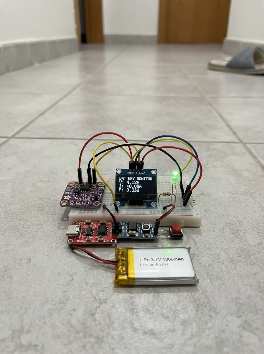
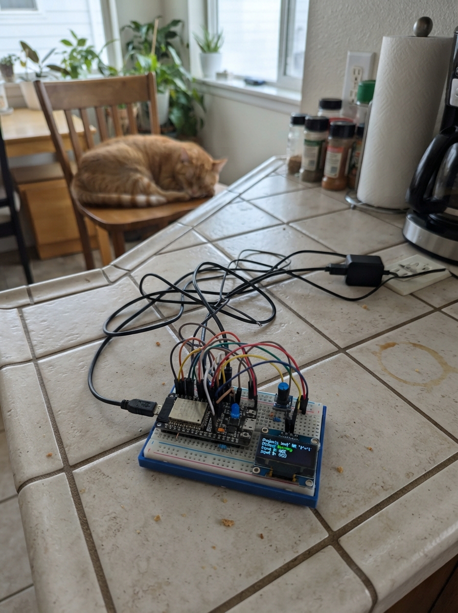
This portable battery monitor combines an ESP32 microcontroller with an INA219 current sensor to track voltage and current draw from a rechargeable LiPo battery in real time. The 0.96" OLED display shows live power metrics while a charming animated character responds to button presses, making battery monitoring both functional and fun. The TP4056 charger module handles safe Li-ion charging via USB Type-C, while a boost converter provides stable 5V power to the ESP32 and display.
This guide provides a complete parts list, wiring diagram, and step-by-step assembly instructions to build your own battery monitor. The included firmware demonstrates I2C communication with the sensor and display, button debouncing, and animated graphics. Once assembled and programmed, the device fits into a compact enclosure and serves as a handy tool for testing power consumption on portable projects.
Wiring diagram

Gather all the parts
Assemble it in 7 steps
1. Prepare the rechargeable power section
With the USB-C charger unplugged, connect the battery positive lead to TP4056 B+ and battery negative lead to B-. Connect TP4056 OUT+ to the MT3608 VIN+ and TP4056 OUT- to MT3608 VIN-.
- Use the TP4056 OUT terminals, not B+ and B-, to power the boost converter; OUT is the protected load connection.
- Have an adult check the battery connector polarity before plugging in USB-C.
- Never short a Li-ion battery or leave its bare leads touching metal.
- Do not let a child connect or charge the battery without adult supervision.
2. Set the boost converter to 5 V
Before connecting the ESP32, power the TP4056 from USB-C and use a multimeter to adjust the MT3608 output to 5.0 V between VOUT+ and VOUT-. Disconnect USB-C after adjustment.
- Turn the small adjustment screw very slowly.
- The ESP32 may be damaged by a boost output set too high.
- Do not connect MT3608 VOUT+ to any ESP32 GPIO pin.
- Only connect the 5 V output to the ESP32 VIN/5V power input through the INA219 as described next.
3. Add the power meter and ESP32 supply
Wire MT3608 VOUT+ to INA219 VIN+. Wire INA219 VIN- to the ESP32 VIN/5V pin. Connect MT3608 VOUT- to ESP32 GND. Connect INA219 VCC to ESP32 3V3 and INA219 GND to ESP32 GND. This places the INA219 in series with the 5 V supply so Buddy can measure its own current.
- All ground connections must be common: boost VOUT-, ESP32 GND, OLED GND, INA219 GND, buttons, and LED cathodes.
- The INA219 signal supply is 3.3 V, even though it measures the 5 V power line.
- Keep VIN+ and VIN- in the stated order; reversing them makes current readings negative.
- Do not power the ESP32 VIN/5V pin from both the boost module and a USB cable at the same time.
4. Connect the OLED face display
Connect OLED VCC to ESP32 3V3 and OLED GND to ESP32 GND. Connect OLED CLK to GPIO 18, DIN to GPIO 23, CS to GPIO 27, DC to GPIO 17, and RES to GPIO 16.
- A 7-pin SPI OLED normally labels its data pin DIN or MOSI; connect the pin labeled DIN/MOSI to GPIO 23.
- Keep the short display wires tidy so the face does not flicker.
- Do not connect a 3.3 V-only OLED VCC pin to the 5 V boost rail.
- If the module labels differ, use the printed functions: CLK/SCK, DIN/MOSI, CS, DC, and RES/RST.
5. Connect the INA219 I2C signals
Connect INA219 SDA to ESP32 GPIO 21 and INA219 SCL to ESP32 GPIO 22. Its VCC and GND connections were made in the power step.
- SDA and SCL are different from the OLED DIN and CLK pins because the OLED is used in SPI mode.
- Most INA219 breakout boards include the needed I2C pull-up resistors.
- Never connect the INA219 VIN+ or VIN- terminals to GPIO 21 or GPIO 22.
6. Add Buddy's buttons and status lights
For the Page button, connect one terminal to GPIO 32 and the other to GND. For the Status button, connect one terminal to GPIO 33 and the other to GND. Connect GPIO 25 to one end of the first 330 ohm resistor, its other end to the green LED anode (long lead), and the green LED cathode (short lead) to GND. Repeat with GPIO 26, the second 330 ohm resistor, and the red LED.
- The firmware uses the ESP32's internal pull-up resistors, so each button needs only a GPIO-to-GND connection.
- Green means the measured 5 V rail is healthy; red means it is low.
- Every LED needs its own 330 ohm series resistor. Do not connect an LED directly to a GPIO.
- If an LED does not light, turn off power and reverse that LED.
7. Power up and make a Buddy enclosure
Ask an adult to inspect every power wire. Turn on power, then use Schematik's Deploy button to flash the project. Press Page to cycle Happy, Silly, Sleepy, and Wow faces. Press Status to show or hide the power meter. Mount the OLED behind a cardboard or plastic face window, leaving the charger USB-C port accessible.
- Label the two buttons with a drawn smiley face and a lightning bolt.
- A cardboard box makes a simple safe case, but keep metal foil and loose wires away from the battery.
- Stop using the project if the battery, charger, or boost converter becomes hot, swells, smells unusual, or is physically damaged.
- Charge only while an adult is present and place the project on a non-flammable surface.
Review all connections
1. Connections between "battery_1" and "ESP32"
2. Connections between "tp4056_1" and "ESP32"
3. Connections between "boost_1" and "ESP32"
4. Connections between "ina219_1" and "ESP32"
5. Connections between "oled_1" and "ESP32"
6. Connections between "button_page_1" and "ESP32"
7. Connections between "button_output_1" and "ESP32"
8. Connections between "resistor_ok_1" and "ESP32"
9. Connections between "led_ok_1" and "ESP32"
10. Connections between "resistor_low_1" and "ESP32"
11. Connections between "led_low_1" and "ESP32"
Deploy the firmware
#include <Arduino.h>
#include <Wire.h>
#include <Adafruit_INA219.h>
#include <Adafruit_GFX.h>
#include <Adafruit_SSD1306.h>

#define INA_SDA 21
#define INA_SCL 22
#define OLED_CLK 18
#define OLED_DIN 23
#define OLED_CS 27
#define OLED_DC 17
#define OLED_RES 16
#define PAGE_BUTTON 32
#define STATUS_BUTTON 33
#define GREEN_LED 25
#define RED_LED 26


// Hoisted type definitions
enum BuddyMood { HAPPY, SILLY, SLEEPY, SURPRISED };


// Forward declarations
bool pressed(uint8_t pin, unsigned long &lastPress);
void drawEye(int x, int y, bool closed, bool surprised);
void drawMouth(BuddyMood mood, int y);
void drawBuddy();
void drawStatus();
void updateMeter();

Adafruit_INA219 ina219;
Adafruit_SSD1306 display(128, 64, OLED_DIN, OLED_CLK, OLED_DC, OLED_RES, OLED_CS);


BuddyMood selectedMood = HAPPY;

float busVoltage = 0.0f;
float loadCurrent = 0.0f;
unsigned long lastMeterRead = 0;
unsigned long lastAnimation = 0;
unsigned long pagePressedAt = 0;
unsigned long statusPressedAt = 0;
bool blinkEyes = false;
bool showStatus = false;
bool sensorFound = false;

bool pressed(uint8_t pin, unsigned long &lastPress) {
  if (digitalRead(pin) == LOW && millis() - lastPress > 250) {
    lastPress = millis();
    return true;
  }
  return false;
}

void drawEye(int x, int y, bool closed, bool surprised) {
  if (closed) {
    display.drawLine(x - 10, y, x + 10, y, SSD1306_WHITE);
    return;
  }
  int height = surprised ? 20 : 16;
  display.fillRoundRect(x - 10, y - height / 2, 20, height, 7, SSD1306_WHITE);
  display.fillCircle(x, y, surprised ? 3 : 4, SSD1306_BLACK);
  if (!surprised) display.fillCircle(x + 1, y - 1, 1, SSD1306_WHITE);
}

void drawMouth(BuddyMood mood, int y) {
  if (mood == HAPPY) {
    display.drawCircle(64, y - 8, 13, SSD1306_WHITE);
    display.fillRect(49, y - 21, 30, 13, SSD1306_BLACK);
  } else if (mood == SILLY) {
    display.drawLine(51, y - 4, 60, y + 3, SSD1306_WHITE);
    display.drawLine(60, y + 3, 69, y - 3, SSD1306_WHITE);
    display.drawLine(69, y - 3, 78, y + 4, SSD1306_WHITE);
    display.fillRoundRect(59, y + 3, 10, 6, 2, SSD1306_WHITE);
  } else if (mood == SLEEPY) {
    display.drawLine(52, y, 76, y, SSD1306_WHITE);
  } else {
    display.drawCircle(64, y - 1, 7, SSD1306_WHITE);
  }
}

const char *moodName(BuddyMood mood) {
  switch (mood) {
    case HAPPY: return "HAPPY";
    case SILLY: return "SILLY";
    case SLEEPY: return "SLEEPY";
    default: return "WOW!";
  }
}

void drawBuddy() {
  bool lowPower = sensorFound && busVoltage < 4.75f;
  BuddyMood faceMood = lowPower ? SLEEPY : selectedMood;
  bool closed = blinkEyes || faceMood == SLEEPY;

  display.clearDisplay();
  display.drawRoundRect(1, 1, 126, 62, 7, SSD1306_WHITE);
  display.setTextColor(SSD1306_WHITE);
  display.setTextSize(1);
  display.setCursor(8, 7);
  display.print("BUDDY: ");
  display.print(lowPower ? "NEEDS CHARGE" : moodName(faceMood));

  drawEye(42, 33, closed, faceMood == SURPRISED);
  drawEye(86, 33, closed, faceMood == SURPRISED);
  drawMouth(faceMood, 52);

  display.setCursor(10, 55);
  display.print("PAGE=mood  STATUS=meter");
  display.display();
}

void drawStatus() {
  display.clearDisplay();
  display.setTextColor(SSD1306_WHITE);
  display.setTextSize(1);
  display.setCursor(0, 0);
  display.println("BUDDY POWER METER");
  display.drawLine(0, 10, 127, 10, SSD1306_WHITE);

  if (!sensorFound) {
    display.setCursor(0, 22);
    display.println("INA219 not found.");
    display.println("Check SDA/SCL wiring.");
  } else {
    display.setTextSize(2);
    display.setCursor(0, 16);
    display.print(busVoltage, 2);
    display.println("V");
    display.setCursor(0, 38);
    display.print(loadCurrent, 0);
    display.println("mA");
    display.setTextSize(1);
    display.setCursor(88, 48);
    display.print(busVoltage * loadCurrent / 1000.0f, 2);
    display.print("W");
  }
  display.setTextSize(1);
  display.setCursor(0, 55);
  display.print("Press STATUS for Buddy");
  display.display();
}

void updateMeter() {
  if (!sensorFound || millis() - lastMeterRead < 500) return;
  lastMeterRead = millis();
  busVoltage = ina219.getBusVoltage_V();
  loadCurrent = ina219.getCurrent_mA();
  if (loadCurrent < 0) loadCurrent = 0;

  bool lowPower = busVoltage < 4.75f;
  digitalWrite(RED_LED, lowPower ? HIGH : LOW);
  digitalWrite(GREEN_LED, lowPower ? LOW : HIGH);
}

void setup() {
  pinMode(PAGE_BUTTON, INPUT_PULLUP);
  pinMode(STATUS_BUTTON, INPUT_PULLUP);
  pinMode(GREEN_LED, OUTPUT);
  pinMode(RED_LED, OUTPUT);
  digitalWrite(GREEN_LED, LOW);
  digitalWrite(RED_LED, LOW);

  Wire.begin(INA_SDA, INA_SCL);
  sensorFound = ina219.begin();

  if (!display.begin(SSD1306_SWITCHCAPVCC)) {
    while (true) { delay(100); }
  }
  display.clearDisplay();
  display.setTextColor(SSD1306_WHITE);
  display.setTextSize(2);
  display.setCursor(18, 20);
  display.println("Hi! ^_^ ");
  display.display();
  delay(1200);
}

void loop() {
  updateMeter();

  if (pressed(PAGE_BUTTON, pagePressedAt)) {
    selectedMood = static_cast<BuddyMood>((selectedMood + 1) % 4);
    showStatus = false;
  }
  if (pressed(STATUS_BUTTON, statusPressedAt)) {
    showStatus = !showStatus;
  }

  if (millis() - lastAnimation > 180) {
    lastAnimation = millis();
    blinkEyes = !blinkEyes;
    if (showStatus) drawStatus();
    else drawBuddy();
  }
}
Remix this project
Make it yours in one click
Open a full copy of this project in your own Schematik workspace — diagram, code, parts, and assembly steps included. Swap the sensor, add features, or redesign the whole thing with AI. The author's original stays untouched.