Community project
Smart Irrigation Gateway
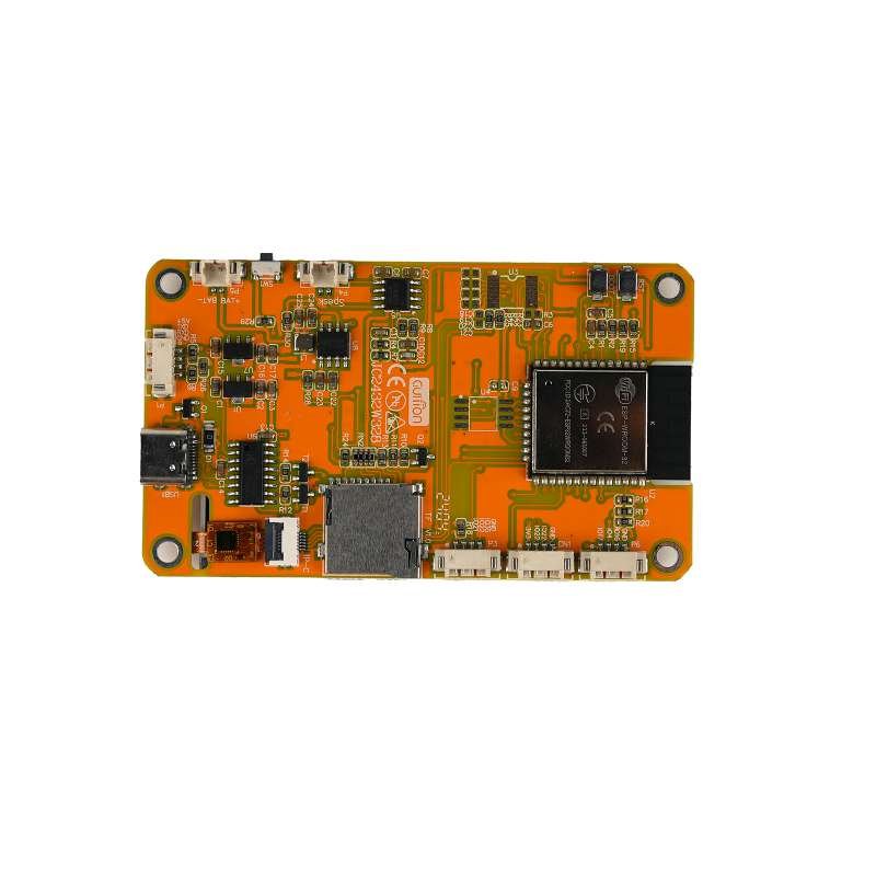
The Smart Irrigation Gateway is a multi-protocol control hub built around an ESP32 that manages up to 16 irrigation zones through dual relay modules. It combines local scheduling with remote connectivity via GSM/GPRS and LoRa radio, allowing operators to monitor and control water distribution from anywhere. The gateway communicates with an STM8S controller to safely switch high-current irrigation loads while maintaining isolated low-voltage logic circuits.
This guide provides a complete wiring diagram, detailed parts list, and step-by-step assembly instructions for integrating the relay boards, GSM modem, LoRa transceiver, and logic-level shifters. You'll also get the Arduino firmware framework that handles serial communication with the STM8 controller, relay switching, radio messaging, and local scheduling logic—ready to customize for your irrigation zones and remote notification needs.
Wiring diagram

Gather all the parts
Assemble it in 6 steps
1. Mount the low-voltage boards
Mount the JC2432W328C gateway board, STM8 relay controller, LoRa module, GSM module, UART bridge, regulator, and relay board in a non-conductive enclosure. Keep the radio antenna and GSM antenna clear of the display and relay wiring.
- Leave access to the JC2432W328C programming USB connector.
- Use short twisted low-voltage wires for the UART connections.
- Do not connect mains wiring while any board is powered. Relay contact terminals can carry dangerous voltage.
2. Make the shared low-voltage power wiring
Connect the protected supply 5V OUT to the STM8 5V pin, relay board VCC, and GSM regulator VIN. Connect the protected supply GND OUT to every board GND pin, including the display board ground, STM8, relay board, LoRa radio, UART bridge, GSM regulator, and GSM module (power and shared ground). Connect the GSM regulator VOUT to the SIM800L VCC pin (4.0 V modem power).
- Use wiring rated for the relay board and GSM modem current.
- Place a 100–470 µF low-ESR capacitor close to SIM800L VCC and GND to handle transmit bursts.
- Do not connect 5 V to the LoRa module or UART bridge 3.3 V pins — that can permanently damage them.
- Do not power the SIM800L directly from the display board; its short current bursts can reset the gateway.
3. Wire the STM8 command link
Connect JC2432W328C GPIO16 to STM8 RX (command data), STM8 TX to JC2432W328C GPIO17 (state data), and keep their grounds connected. The STM8 board controls all eight relay inputs and its own local buttons and LEDs; do not wire relay inputs to ESP32 GPIO pins.
- Cross the two serial data wires: transmitter goes to receiver.
- Use a 3.3 V-compatible STM8 UART interface; add a level shifter if your STM8 board drives TX at 5 V.
- A 5 V STM8 TX signal connected directly to the ESP32 RX pin can damage the ESP32; confirm the STM8 board UART voltage first.
4. Wire the LoRa radio
Connect LoRa VCC to 3V3, GND to GND, SCK to GPIO18, MISO to GPIO19, MOSI to GPIO23, NSS to GPIO26, NRST to GPIO25, and BUSY to GPIO32 (radio power, ground, data, select, reset, and ready signals). Leave DIO1 unconnected for the supplied polling starter firmware.
- Fit the correct approved antenna before transmitting.
- Keep SPI wires short and away from relay contact wiring.
- Use only the radio frequency variant allowed in your country.
- Do not transmit without a suitable antenna connected; that can damage the radio transmitter.
5. Wire the GSM bridge and modem
Connect UART bridge VCC to 3V3, GND to GND, SDA to GPIO21, and SCL to GPIO22 (bridge power, ground, and control data). Connect bridge TXA to SIM800L RX through a 3.3 V-to-2.8 V level shifter or divider, and SIM800L TX to bridge RXA (modem data).
- Insert an activated SIM and attach the GSM antenna before testing the modem.
- Keep modem power wires short and thick enough for its current bursts.
- Do not feed the SIM800L RX pin directly from a 3.3 V transmitter unless your exact SIM800L carrier documentation permits it; use the level reduction described above.
6. Connect irrigation loads safely
Have a qualified person connect each irrigation valve or pump control circuit to the appropriate relay COM and NO/NC terminals, with a suitable fuse, enclosure, isolation, and load-rated cable. Label channels R1 through R8 to match the zones in the touchscreen.
- Test each relay with a low-voltage lamp or meter before connecting irrigation equipment.
- Keep mains/load wires physically separated from all low-voltage signal wiring.
- Relay contact wiring may be mains voltage and can cause fatal shock or fire. Only a qualified person should install it.
Review all connections
1. Connections between "power_supply" and "ESP32"
2. Connections between "stm8_relay_controller" and "ESP32"
3. Connections between "relay_bank" and "ESP32"
4. Connections between "gsm_regulator" and "ESP32"
5. Connections between "gsm" and "ESP32"
6. Connections between "uart_bridge" and "ESP32"
7. Connections between "lora" and "ESP32"
8. Connections between "stm8_level_shifter" and "ESP32"
Deploy the firmware
#include <Arduino.h>
#include <Wire.h>
#include <WiFi.h>
#include <lvgl.h>
#include "config/pins.h"
#include "services/stm8_link.h"
#include "services/relay_service.h"
#include "services/radio_service.h"
#include "services/gsm_service.h"
#include "storage/config_store.h"
#include "ui/gateway_ui.h"

#define STM8_RX 17
#define STM8_TX 16
#define I2C_SDA 21
#define I2C_SCL 22

// JC2432W328C display and capacitive-touch initialization is board-revision-specific.
// Keep it in the display adapter when the verified vendor pin map is available.
// lv_init() is safe here; GatewayUi owns only widgets, never the hardware driver.


// Forward declarations
static bool localClock(uint8_t& weekday, uint16_t& minuteOfDay);

HardwareSerial stm8Serial(2);
Stm8Link stm8;
RelayService relays;
RadioService lora;
GsmService gsm;
ConfigStore store;
GatewayUi ui;
GatewayStatus gateway{};

uint32_t lastSchedulerMinute = UINT32_MAX;
uint32_t lastUiRefresh = 0;

static bool localClock(uint8_t& weekday, uint16_t& minuteOfDay) {
  // Replace with SNTP or RTC adapter. The scheduler remains inhibited until time is trusted.
  time_t now = time(nullptr);
  if (now < 1700000000) return false;
  tm local{};
  localtime_r(&now, &local);
  weekday = local.tm_wday;
  minuteOfDay = local.tm_hour * 60 + local.tm_min;
  return true;
}

void setup() {
  Serial.begin(115200);
  Wire.begin(Pins::I2C_SDA, Pins::I2C_SCL);
  stm8Serial.begin(115200, SERIAL_8N1, Pins::STM8_RX, Pins::STM8_TX);
  stm8.begin(stm8Serial);
  store.begin();
  relays.begin(stm8);
  lora.begin();
  gsm.begin();
  lv_init();
  // TODO (board verified): initialize ST7789 flush callback and capacitive-touch read callback.
  ui.begin();
  WiFi.mode(WIFI_STA);  // credentials are intentionally stored/configured outside source code
}

void loop() {
  stm8.tick();
  lora.tick();
  gsm.tick();
  const uint32_t now = millis();
  uint8_t weekday = 0;
  uint16_t minute = 0;
  const bool clockValid = localClock(weekday, minute);
  if (clockValid && minute != lastSchedulerMinute) {
    lastSchedulerMinute = minute;
    relays.tick(weekday, minute, true);
  } else if (!clockValid) {
    relays.tick(0, 0, false); // applies STM8 button reports and fail-safe timeouts only
  }
  gateway.stm8Online = stm8.online();
  gateway.loraOnline = lora.online();
  gateway.gsmOnline = gsm.online();
  gateway.wifiOnline = WiFi.status() == WL_CONNECTED;
  gateway.rssi = gateway.wifiOnline ? WiFi.RSSI() : 0;
  if (now - lastUiRefresh >= 250) {
    lastUiRefresh = now;
    RelayModel view[8];
    for (uint8_t i = 0; i < 8; ++i) view[i] = relays.at(i);
    ui.update(view, gateway);
  }
  ui.tick();
  delay(2); // yields to Wi-Fi/LVGL without blocking communication state machines
}
Remix this project
Make it yours in one click
Open a full copy of this project in your own Schematik workspace — diagram, code, parts, and assembly steps included. Swap the sensor, add features, or redesign the whole thing with AI. The author's original stays untouched.