Community project
WiFi Video TFT Display
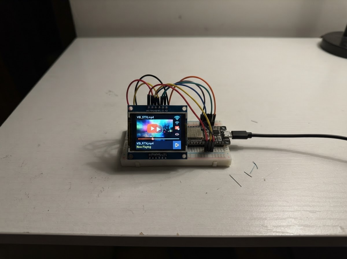
This project turns an ESP32 and a 2.0-inch ST7789 TFT display into a WiFi-connected video receiver. The device creates its own access point and listens for incoming video frames sent over UDP, displaying them on the small color screen in real time.
The guide includes a complete wiring diagram showing SPI connections between the ESP32 and display, a full parts list, and firmware that handles WiFi setup, packet reassembly, and display rendering. Assembly takes about 15 minutes and requires only basic soldering skills.
Wiring diagram

Gather all the parts
Assemble it in 4 steps
1. Prepare the 3.3 V parts
Place the ESP32-S3-DevKitC-1-N8R8 and the tft_1 display where their headers can be connected with short jumper wires. Power the board only from its USB connector while building.
- This design requires the N8R8 version with 8 MB OPI PSRAM; the display has two full 320×240 RGB565 buffers stored in PSRAM.
- Do not use a non-PSRAM ESP32-S3 board: the firmware intentionally stops if PSRAM is absent.
- Use 3.3 V logic and supply for the TFT connections.
2. Connect power and ground
Wire tft_1 VCC to the ESP32-S3 3V3 rail, and wire tft_1 GND to an ESP32-S3 GND rail.
- A shared ground is mandatory for the SPI data signals to work.
- Do not connect the TFT VCC to the board VIN/5 V rail for this build.
3. Connect the SPI display signals
Connect tft_1 SCK to GPIO12, MOSI to GPIO11, CS to GPIO10, DC to GPIO14, RST to GPIO15, and BL to GPIO16 on the ESP32-S3 board.
- Keep SCK and MOSI short and routed away from the antenna area where practical.
- The TFT MISO and SDCS pins are intentionally unused because this is a write-only display and its microSD socket is not used.
- Check the labels on the TFT carefully: MOSI may also be printed as DIN or SDA; DC may be printed as A0. Do not confuse the TFT SDA label with I2C SDA.
4. Power and start video reception
Connect the ESP32-S3 board to USB power. After deploying the firmware using Schematik’s Deploy button, connect the video sender to the Wi-Fi network named TFT-Video using password display123. Send UDP packets to 192.168.4.1 port 5000.
- Each UDP datagram is a 12-byte little-endian header followed by up to 1024 bytes of RGB565 pixels. Header fields are: magic 0x54465456 (uint32), frame ID (uint16), chunk index (uint16), chunk count 150 (uint16), and payload byte count (uint16). Chunks map to byte offset chunkIndex × 1024. The final chunk has 512 payload bytes.
- The sender must send exactly 150 chunks for each 320×240 frame (153,600 bytes), and should advance frame ID each new frame. Frames may arrive out of order; all chunks must arrive before the display changes.
- Change the access-point password in the firmware before using this outside a controlled setting.
- UDP has no delivery guarantee; lost chunks cause that frame to be dropped rather than showing corrupted or partial video.
Review all connections
1. Connections between "tft_1" and "ESP32"
Deploy the firmware
#include <Arduino.h>

// Browser-simulator facade. The deployed ESP32 code below still uses Wi-Fi,
// PSRAM, UDP, and the physical ST7789 over SPI.
#if !defined(ESP32)

// Hoisted type definitions
struct __attribute__((packed)) VideoPacketHeader {
  uint32_t magic;
  uint16_t frameId;
  uint16_t chunkIndex;
  uint16_t chunkCount;
  uint16_t payloadBytes;
};


// Forward declarations
static void tftCommand(uint8_t command);
static void tftData(const uint8_t *data, size_t length);
static void tftInit();
static void setWindow(uint16_t x, uint16_t y, uint16_t width, uint16_t height);
static void showFrontBuffer();
static bool isChunkReceived(uint16_t index);
static void markChunkReceived(uint16_t index);
static void startFrame(uint16_t frameId, uint16_t chunkCount);
static void receiveVideo();

void setup() {
  Serial.begin(115200);
  Serial.println("ESP32 TFT Wi-Fi video receiver hardware build required");
}
void loop() { delay(1000); }
#else

#include <WiFi.h>
#include <WiFiUdp.h>
#include <SPI.h>
#include "esp_heap_caps.h"


static const char *AP_SSID = "TFT-Video";
static const char *AP_PASSWORD = "display123";
static constexpr uint16_t VIDEO_PORT = 5000;
static constexpr uint16_t SCREEN_W = 320;
static constexpr uint16_t SCREEN_H = 240;
static constexpr size_t FRAME_BYTES = SCREEN_W * SCREEN_H * sizeof(uint16_t);
static constexpr uint16_t MAX_PAYLOAD = 1024;
static constexpr uint16_t MAX_CHUNKS = (FRAME_BYTES + MAX_PAYLOAD - 1) / MAX_PAYLOAD;
static constexpr uint32_t PACKET_MAGIC = 0x54465456UL;

static const int TFT_SCK = 12;
static const int TFT_MOSI = 11;
static const int TFT_CS = 10;
static const int TFT_DC = 14;
static const int TFT_RST = 15;
static const int TFT_BL = 16;

static constexpr uint8_t CMD_SWRESET = 0x01;
static constexpr uint8_t CMD_SLPOUT = 0x11;
static constexpr uint8_t CMD_COLMOD = 0x3A;
static constexpr uint8_t CMD_MADCTL = 0x36;
static constexpr uint8_t CMD_CASET = 0x2A;
static constexpr uint8_t CMD_RASET = 0x2B;
static constexpr uint8_t CMD_RAMWR = 0x2C;
static constexpr uint8_t CMD_DISPON = 0x29;

static_assert(sizeof(VideoPacketHeader) == 12, "Unexpected packet header size");

WiFiUDP udp;
uint16_t *frontBuffer = nullptr;
uint16_t *backBuffer = nullptr;
uint8_t receivedChunks[(MAX_CHUNKS + 7) / 8] = {};
uint16_t receivingFrameId = 0;
uint16_t expectedChunks = 0;
uint16_t receivedChunkCount = 0;
bool haveReceivingFrame = false;

static void tftCommand(uint8_t command) {
  digitalWrite(TFT_DC, LOW);
  digitalWrite(TFT_CS, LOW);
  SPI.transfer(command);
  digitalWrite(TFT_CS, HIGH);
}

static void tftData(const uint8_t *data, size_t length) {
  digitalWrite(TFT_DC, HIGH);
  digitalWrite(TFT_CS, LOW);
  SPI.writeBytes(data, length);
  digitalWrite(TFT_CS, HIGH);
}

static void tftInit() {
  digitalWrite(TFT_RST, LOW);
  delay(20);
  digitalWrite(TFT_RST, HIGH);
  delay(120);
  tftCommand(CMD_SWRESET); delay(150);
  tftCommand(CMD_SLPOUT); delay(120);
  const uint8_t colorMode = 0x55;
  tftCommand(CMD_COLMOD); tftData(&colorMode, 1);
  // Landscape, RGB color order. This matches the former setRotation(1) display orientation.
  const uint8_t madctl = 0x60;
  tftCommand(CMD_MADCTL); tftData(&madctl, 1);
  tftCommand(CMD_DISPON); delay(20);
}

static void setWindow(uint16_t x, uint16_t y, uint16_t width, uint16_t height) {
  uint8_t data[4] = {uint8_t(x >> 8), uint8_t(x), uint8_t((x + width - 1) >> 8), uint8_t(x + width - 1)};
  tftCommand(CMD_CASET); tftData(data, sizeof(data));
  data[0] = uint8_t(y >> 8); data[1] = uint8_t(y);
  data[2] = uint8_t((y + height - 1) >> 8); data[3] = uint8_t(y + height - 1);
  tftCommand(CMD_RASET); tftData(data, sizeof(data));
}

static void showFrontBuffer() {
  setWindow(0, 0, SCREEN_W, SCREEN_H);
  digitalWrite(TFT_DC, LOW);
  digitalWrite(TFT_CS, LOW);
  SPI.transfer(CMD_RAMWR);
  digitalWrite(TFT_DC, HIGH);
  // The incoming RGB565 payload is already byte-ordered for the ST7789.
  SPI.writeBytes(reinterpret_cast<const uint8_t *>(frontBuffer), FRAME_BYTES);
  digitalWrite(TFT_CS, HIGH);
}

static bool isChunkReceived(uint16_t index) {
  return (receivedChunks[index >> 3] & (1U << (index & 7))) != 0;
}
static void markChunkReceived(uint16_t index) {
  receivedChunks[index >> 3] |= (1U << (index & 7));
}
static void startFrame(uint16_t frameId, uint16_t chunkCount) {
  memset(receivedChunks, 0, sizeof(receivedChunks));
  receivingFrameId = frameId;
  expectedChunks = chunkCount;
  receivedChunkCount = 0;
  haveReceivingFrame = true;
}

static void receiveVideo() {
  int packetSize;
  while ((packetSize = udp.parsePacket()) > 0) {
    if (packetSize < (int)sizeof(VideoPacketHeader) || packetSize > (int)(sizeof(VideoPacketHeader) + MAX_PAYLOAD)) {
      while (udp.available()) udp.read();
      continue;
    }
    VideoPacketHeader header;
    if (udp.read(reinterpret_cast<uint8_t *>(&header), sizeof(header)) != sizeof(header) ||
        header.magic != PACKET_MAGIC || header.chunkCount != MAX_CHUNKS ||
        header.chunkIndex >= header.chunkCount || header.payloadBytes == 0 || header.payloadBytes > MAX_PAYLOAD ||
        packetSize != (int)(sizeof(header) + header.payloadBytes)) {
      while (udp.available()) udp.read();
      continue;
    }
    const size_t byteOffset = (size_t)header.chunkIndex * MAX_PAYLOAD;
    const size_t expectedBytes = min((size_t)MAX_PAYLOAD, FRAME_BYTES - byteOffset);
    if (byteOffset >= FRAME_BYTES || header.payloadBytes != expectedBytes) {
      while (udp.available()) udp.read();
      continue;
    }
    if (!haveReceivingFrame || header.frameId != receivingFrameId) startFrame(header.frameId, header.chunkCount);
    uint8_t *destination = reinterpret_cast<uint8_t *>(backBuffer) + byteOffset;
    if (udp.read(destination, header.payloadBytes) != header.payloadBytes) continue;
    if (!isChunkReceived(header.chunkIndex)) {
      markChunkReceived(header.chunkIndex);
      ++receivedChunkCount;
    }
    if (receivedChunkCount == expectedChunks) {
      uint16_t *oldFront = frontBuffer;
      frontBuffer = backBuffer;
      backBuffer = oldFront;
      haveReceivingFrame = false;
      showFrontBuffer();
    }
  }
}

void setup() {
  Serial.begin(115200);
  pinMode(TFT_BL, OUTPUT); pinMode(TFT_CS, OUTPUT); pinMode(TFT_DC, OUTPUT); pinMode(TFT_RST, OUTPUT);
  digitalWrite(TFT_BL, HIGH);
  SPI.begin(TFT_SCK, -1, TFT_MOSI, TFT_CS);
  SPI.beginTransaction(SPISettings(40000000, MSBFIRST, SPI_MODE0));
  tftInit();
  if (!psramFound()) {
    Serial.println("PSRAM not found");
    while (true) delay(1000);
  }
  frontBuffer = static_cast<uint16_t *>(heap_caps_malloc(FRAME_BYTES, MALLOC_CAP_SPIRAM | MALLOC_CAP_8BIT));
  backBuffer = static_cast<uint16_t *>(heap_caps_malloc(FRAME_BYTES, MALLOC_CAP_SPIRAM | MALLOC_CAP_8BIT));
  if (!frontBuffer || !backBuffer) {
    Serial.println("PSRAM allocation failed");
    while (true) delay(1000);
  }
  memset(frontBuffer, 0, FRAME_BYTES);
  memset(backBuffer, 0, FRAME_BYTES);
  showFrontBuffer();
  WiFi.mode(WIFI_AP);
  WiFi.softAP(AP_SSID, AP_PASSWORD);
  udp.begin(VIDEO_PORT);
  Serial.printf("AP %s, UDP port %u, IP %s\n", AP_SSID, VIDEO_PORT, WiFi.softAPIP().toString().c_str());
}

void loop() { receiveVideo(); }
#endif
Remix this project
Make it yours in one click
Open a full copy of this project in your own Schematik workspace — diagram, code, parts, and assembly steps included. Swap the sensor, add features, or redesign the whole thing with AI. The author's original stays untouched.