Community project
AI Facial Recognition Gimbal Robot
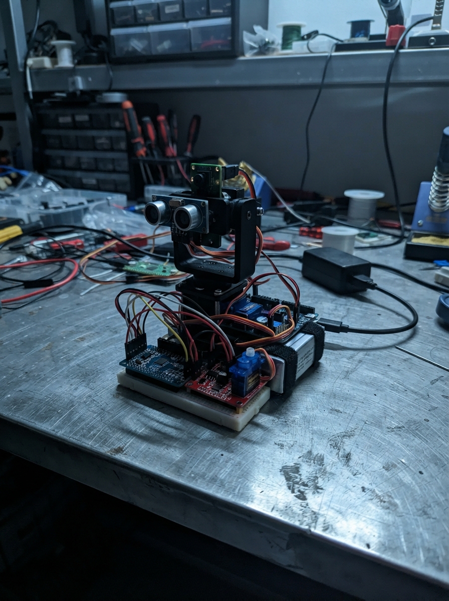
This project builds a two-wheeled rover robot with an articulated pan-and-tilt head, capable of obstacle detection and edge avoidance for safe tabletop operation. The robot uses an ESP32 microcontroller to coordinate dual N20 motors with encoder feedback, servo-driven head movement via a PCA9685 driver, and multiple safety sensors including IR cliff detectors and a distance rangefinder.
The guide provides a complete wiring diagram, full parts list, and step-by-step assembly instructions for constructing the chassis, mounting the pan-tilt mechanism, and integrating all motor drivers and sensors. Included firmware implements motor speed control with PID feedback, head tracking with emotional state expressions, and autonomous patrol behavior with obstacle avoidance—giving makers a foundation for further customization and sensor integration.
Wiring diagram

Gather all the parts
Assemble it in 11 steps
1. Build the rover base
Screw left_motor and right_motor onto opposite sides of rover_base with both output shafts facing outward. Push one wheel onto each shaft. Screw caster under the other end of rover_base so all three wheels touch a flat table. Strap drive_battery low and near the center of the base so it cannot slide into a wheel.
- Put the caster at the rear and the Tab5 head toward the front; this gives the camera a clear forward view.
- Keep the battery away from sharp screw tips and moving wheels — a pierced LiPo battery can catch fire.
2. Build the moving head
Screw pan_servo into the fixed lower part of pan_tilt_bracket, then screw tilt_servo to the moving pan section. Fasten the Tab5 securely to the tilt plate with the camera facing forward. Fit each servo horn only after the firmware has centered the servos.
- Leave a loose loop of cable so the display can turn fully left, right, up, and down.
- Do not force a powered servo by hand — it can strip its small gears or pinch fingers.
3. Mount the table-safety sensors
Screw cliff_left, cliff_center, and cliff_right underneath the front of rover_base, with their dark sensor windows 5 to 15 mm above the table. Put one near each front corner and one in the middle. Point front_range straight ahead above the bumper, where the wheels and bracket cannot block its view.
- The three downward sensors look for the table surface; the forward sensor looks for people, walls, and other objects.
- Do not start autonomous driving until these sensors have been mounted and calibrated — a camera alone cannot reliably stop a robot from falling off a table.
4. Wire the Tab5 to the control boards
With all power unplugged, connect servo_driver VCC to Tab5 3V3 (power), servo_driver GND to Tab5 GND (ground), servo_driver SDA to Port A SDA / GPIO53 (data), and servo_driver SCL to Port A SCL / GPIO54 (clock). Connect motor_driver VCC to Tab5 3V3 (power), motor_driver GND to Tab5 GND (ground), AIN1 to GPIO3 (left direction), AIN2 to GPIO4 (left direction), PWMA to GPIO2 (left speed), BIN1 to GPIO48 (right direction), BIN2 to GPIO47 (right direction), PWMB to GPIO35 (right speed), and STBY to GPIO51 (motor-driver enable).
- Use the Tab5 M5-Bus/GPIO breakout for the rover wires; Port A remains the shared control socket for the servo driver and forward distance sensor.
- Do not put 5 V into any Tab5 GPIO or 3V3 pin — that can permanently damage the Tab5.
5. Wire the edge and distance sensors
Connect each cliff sensor VCC to Tab5 3V3 (power) and GND to Tab5 GND (ground). Connect cliff_left DO to GPIO0 (edge signal), cliff_center DO to GPIO1 (edge signal), and cliff_right DO to GPIO49 (edge signal). Connect front_range VIN to Tab5 3V3 (power), GND to Tab5 GND (ground), SDA to GPIO53 (data), and SCL to GPIO54 (clock).
- The PCA9685 and front_range share GPIO53 and GPIO54 safely because each has its own I2C address.
- Use a VL53L0X breakout that accepts 3.3 V power and 3.3 V I2C signals; a 5 V-only breakout can damage the Tab5.
6. Connect the wheel motors and encoders
Connect motor_driver A01 to left_motor M+ (motor power), A02 to left_motor M- (motor power), B01 to right_motor M+ (motor power), and B02 to right_motor M- (motor power). Connect left_motor ENC_A to GPIO16 (position signal), left_motor ENC_B to GPIO17 (position signal), right_motor ENC_A to GPIO45 (position signal), and right_motor ENC_B to GPIO52 (position signal). Connect both encoder ENC_VCC pins to Tab5 3V3 (power) and both ENC_GND pins to Tab5 GND (ground).
- If forward later makes one wheel turn backward, swap that motor's M+ and M- wires with all power removed.
- Keep motor wires away from the display hinge so they cannot snag while the head moves.
7. Set the wheel-motor voltage
Connect drive_battery BAT+ to drive_buck VIN+ (battery power) and drive_battery BAT- to drive_buck VIN- (ground). Before connecting the motor driver, use a multimeter to adjust drive_buck so VOUT+ to VOUT- measures exactly 6.0 V. Then connect VOUT+ to motor_driver VM (motor power) and run a short, thick wire from VOUT- to the single shared ground point beside drive_buck.
- Mark the buck converter adjustment screw after setting 6.0 V so it is not changed accidentally.
- A fully charged 2-cell battery is about 8.4 V. Do not connect it directly to the 6 V N20 motors — the extra voltage can overheat or shorten their life.
8. Make one shared ground point
Make one sturdy shared ground point beside drive_buck VOUT-. Run the short, thick motor_driver ground return to this point. Also run the servo_usb_breakout GND return to this point, then run one separate lighter ground wire from this point to Tab5 GND and the PCA9685 logic ground.
- Use a small screw terminal block or a soldered distribution joint covered with heat-shrink so the ground wires cannot pull apart.
- Do not omit the Tab5 ground link — without it, the servo and motor control signals may behave unpredictably.
9. Connect the separate head-servo supply
Connect servo_supply +5V to servo_usb_breakout VBUS (power) and servo_supply GND to servo_usb_breakout GND (ground). Connect that breakout VBUS to servo_driver V+ (servo power) and its GND return to the shared ground point. Plug pan_servo into PCA9685 channel 0 and tilt_servo into channel 1: brown or black to GND (ground), red to V+ 5 V (power), and orange or yellow to signal (control).
- The PCA9685 VCC pin stays connected to Tab5 3V3; only its V+ pin receives 5 V servo power.
- Never connect the separate 5 V servo supply to the Tab5 USB-C port or 3V3 pin — this can damage the Tab5.
10. Calibrate the table-edge sensors
With the rover lifted and all three cliff sensors above the same tabletop, turn each tiny adjustment screw until its indicator changes at the table surface. Then slowly move one sensor past the table edge: its indicator must change before the wheel reaches the edge. Repeat for all three sensors.
- Use a small screwdriver and move only a little at a time. A white table, black table, glass, and patterned surface reflect infrared differently.
- If any sensor does not clearly change at the edge, do not use autonomous mode on that table — the robot can fall.
11. Test safety before autonomous movement
Keep the rover lifted, plug the Tab5 into its own USB-C cable, power the servos, and connect the drive battery. Deploy the firmware, then send X to confirm the wheels stop. Place the rover on a large clear table, send A to begin a slow patrol, and keep one hand ready to remove drive power during the first test.
- Put a soft box or folded towel below the table edge during the first test. The robot begins in a stopped state after every power-up.
- Never use autonomous mode near stairs, people’s feet, loose cables, liquids, or a table edge that has not passed the sensor test.
Review all connections
1. Connections between "servo_driver" and "ESP32"
2. Connections between "servo_supply" and "ESP32"
3. Connections between "servo_usb_breakout" and "ESP32"
4. Connections between "pan_servo" and "ESP32"
5. Connections between "tilt_servo" and "ESP32"
6. Connections between "drive_battery" and "ESP32"
7. Connections between "drive_buck" and "ESP32"
8. Connections between "motor_driver" and "ESP32"
9. Connections between "left_motor" and "ESP32"
10. Connections between "right_motor" and "ESP32"
11. Connections between "cliff_left" and "ESP32"
12. Connections between "cliff_center" and "ESP32"
13. Connections between "cliff_right" and "ESP32"
14. Connections between "front_range" and "ESP32"
Deploy the firmware
#include <M5Unified.h>
#include <Wire.h>
#include <Adafruit_PWMServoDriver.h>
#include <Adafruit_VL53L0X.h>

static constexpr int PCA_SDA_PIN=53,PCA_SCL_PIN=54,LEFT_IN1_PIN=3,LEFT_IN2_PIN=4,LEFT_PWM_PIN=2,RIGHT_IN1_PIN=48,RIGHT_IN2_PIN=47,RIGHT_PWM_PIN=35,MOTOR_STBY_PIN=51,LEFT_ENC_A_PIN=16,LEFT_ENC_B_PIN=17,RIGHT_ENC_A_PIN=45,RIGHT_ENC_B_PIN=52,CLIFF_LEFT_PIN=0,CLIFF_CENTER_PIN=1,CLIFF_RIGHT_PIN=49;
static constexpr uint8_t PCA_ADDRESS=0x40,PAN_CHANNEL=0,TILT_CHANNEL=1,MOTOR_PWM_BITS=8;
static constexpr uint16_t SERVO_MIN_TICKS=110,SERVO_MAX_TICKS=510,STOP_DISTANCE_MM=280;
static constexpr uint32_t FACE_FRAME_MS=50,MOTOR_PWM_HZ=20000,PID_INTERVAL_MS=20,TURN_TIME_MS=650,BACK_UP_TIME_MS=450;
static constexpr int16_t PATROL_TICKS=4;
static constexpr int CLIFF_TRIGGER_LEVEL=HIGH; // Set each TCRT5000 trimmer so DO is LOW over the tabletop.

Adafruit_PWMServoDriver servoDriver(PCA_ADDRESS);
Adafruit_VL53L0X rangeSensor;
enum Emotion { HAPPY,CURIOUS,LISTENING,REGISTERING,THINKING,ALERT,PATROLLING };
enum RobotMode { SAFE_STOP,PATROL,AVOID_BACKUP,AVOID_TURN,PERSON_WAIT,GREETING };
struct Pid { int32_t previous=0; float integral=0,previousError=0; int output=120; };
volatile int32_t leftEncoderCount=0,rightEncoderCount=0;
Pid leftPid,rightPid;
Emotion emotion=HAPPY;
RobotMode mode=SAFE_STOP;
int16_t leftTarget=0,rightTarget=0;
int panAngle=90,tiltAngle=90;
uint32_t lastFace=0,lastPid=0,lastThink=0,modeAt=0,lastRange=0,frame=0;
uint16_t frontDistance=8190;
bool rangeAvailable=false;
String statusLine="Starting autonomous patrol...";

void IRAM_ATTR onLeftEncoderA(){leftEncoderCount+=digitalRead(LEFT_ENC_A_PIN)==digitalRead(LEFT_ENC_B_PIN)?1:-1;}
void IRAM_ATTR onRightEncoderA(){rightEncoderCount+=digitalRead(RIGHT_ENC_A_PIN)==digitalRead(RIGHT_ENC_B_PIN)?1:-1;}
void motor(int a,int b,int p,int s){s=constrain(s,-255,255);digitalWrite(a,s>0);digitalWrite(b,s<0);ledcWrite(p,abs(s));}
void targets(int l,int r){leftTarget=l;rightTarget=r;}
void stopRover(){targets(0,0);motor(LEFT_IN1_PIN,LEFT_IN2_PIN,LEFT_PWM_PIN,0);motor(RIGHT_IN1_PIN,RIGHT_IN2_PIN,RIGHT_PWM_PIN,0);}
void pidOne(Pid &p,int32_t count,int target,int a,int b,int pwm){int32_t measured=count-p.previous;p.previous=count;if(!target){p.integral=0;p.previousError=0;p.output=120;motor(a,b,pwm,0);return;}float e=abs(target)-abs(measured);p.integral=constrain(p.integral+e,-80.0f,80.0f);p.output=constrain((int)(p.output+10.0f*e+0.45f*p.integral+3.0f*(e-p.previousError)),45,255);p.previousError=e;motor(a,b,pwm,target>0?p.output:-p.output);}
void updatePid(){if(millis()-lastPid<PID_INTERVAL_MS)return;lastPid=millis();noInterrupts();int32_t l=leftEncoderCount,r=rightEncoderCount;interrupts();pidOne(leftPid,l,leftTarget,LEFT_IN1_PIN,LEFT_IN2_PIN,LEFT_PWM_PIN);pidOne(rightPid,r,rightTarget,RIGHT_IN1_PIN,RIGHT_IN2_PIN,RIGHT_PWM_PIN);}
uint16_t servoTicks(int a){return map(constrain(a,25,155),0,180,SERVO_MIN_TICKS,SERVO_MAX_TICKS);}
void gimbal(int pan,int tilt){panAngle=constrain(pan,25,155);tiltAngle=constrain(tilt,40,140);servoDriver.setPWM(PAN_CHANNEL,0,servoTicks(panAngle));servoDriver.setPWM(TILT_CHANNEL,0,servoTicks(tiltAngle));}
void drawStatic(){M5.Display.fillScreen(TFT_NAVY);M5.Display.setTextDatum(middle_center);M5.Display.setTextColor(TFT_WHITE,TFT_NAVY);M5.Display.setTextSize(2);M5.Display.drawString("Mochi Campus Rover",M5.Display.width()/2,52);}
void drawFace(){int w=M5.Display.width(),h=M5.Display.height(),ey=h/2-45,lx=w/2-150,rx=w/2+150;bool blink=(frame%100)<2;M5.Display.fillRect(lx-80,ey-85,160,170,TFT_NAVY);M5.Display.fillRect(rx-80,ey-85,160,170,TFT_NAVY);M5.Display.fillRect(w/2-380,h/2+35,760,190,TFT_NAVY);if(blink||emotion==LISTENING){M5.Display.drawLine(lx-45,ey,lx+45,ey,TFT_WHITE);M5.Display.drawLine(rx-45,ey,rx+45,ey,TFT_WHITE);}else{M5.Display.fillCircle(lx,ey,48,TFT_WHITE);M5.Display.fillCircle(rx,ey,48,TFT_WHITE);M5.Display.fillCircle(lx,ey+8,18,TFT_NAVY);M5.Display.fillCircle(rx,ey+8,18,TFT_NAVY);}M5.Display.setTextDatum(middle_center);M5.Display.setTextColor(TFT_WHITE,TFT_NAVY);M5.Display.setTextSize(2);M5.Display.drawString(statusLine,w/2,h-115);if(emotion==ALERT)M5.Display.drawCircle(w/2,h/2+80,30,TFT_RED);else if(emotion==HAPPY)M5.Display.drawArc(w/2,h/2+60,85,82,20,160,TFT_WHITE);else if(emotion==CURIOUS)M5.Display.drawCircle(w/2,h/2+80,30,TFT_WHITE);else M5.Display.drawLine(w/2-55,h/2+80,w/2+55,h/2+80,TFT_WHITE);}
bool cliff(){return digitalRead(CLIFF_LEFT_PIN)==CLIFF_TRIGGER_LEVEL||digitalRead(CLIFF_CENTER_PIN)==CLIFF_TRIGGER_LEVEL||digitalRead(CLIFF_RIGHT_PIN)==CLIFF_TRIGGER_LEVEL;}
void range(){if(!rangeAvailable||millis()-lastRange<80)return;lastRange=millis();VL53L0X_RangingMeasurementData_t m;rangeSensor.rangingTest(&m,false);frontDistance=m.RangeStatus!=4?m.RangeMilliMeter:8190;}
void setMode(RobotMode m){mode=m;modeAt=millis();}
void avoid(){stopRover();emotion=ALERT;statusLine="Edge or obstacle - backing away";gimbal(90,105);setMode(AVOID_BACKUP);}
void autonomy(){range();if(mode==SAFE_STOP||mode==PERSON_WAIT||mode==GREETING){stopRover();return;}if(cliff()||(rangeAvailable&&frontDistance<STOP_DISTANCE_MM)){avoid();return;}if(mode==PATROL){emotion=PATROLLING;statusLine="Patrolling - searching for a person";targets(PATROL_TICKS,PATROL_TICKS);}else if(mode==AVOID_BACKUP){targets(-PATROL_TICKS,-PATROL_TICKS);if(millis()-modeAt>=BACK_UP_TIME_MS){statusLine="Turning away safely";setMode(AVOID_TURN);}}else if(mode==AVOID_TURN){targets(PATROL_TICKS,-PATROL_TICKS);if(millis()-modeAt>=TURN_TIME_MS){gimbal(90,90);setMode(PATROL);}}}
void gateway(String s){s.trim();if(s=="A"||s=="AUTONOMY ON"){emotion=PATROLLING;statusLine="Patrolling - searching for a person";gimbal(90,85);setMode(PATROL);}else if(s=="X"||s=="AUTONOMY OFF"){emotion=ALERT;statusLine="Safety stop";setMode(SAFE_STOP);}else if(s.startsWith("PERSON:KNOWN:")){statusLine="Welcome back, "+s.substring(13)+"!";emotion=HAPPY;gimbal(90,90);setMode(GREETING);}else if(s=="PERSON:UNKNOWN"){statusLine="Hello! May I register you?";emotion=CURIOUS;gimbal(105,88);setMode(PERSON_WAIT);}else if(s=="REGISTERING"){statusLine="Please look at me and say your name";emotion=REGISTERING;gimbal(90,98);setMode(PERSON_WAIT);}else if(s.startsWith("REGISTERED:")){statusLine="Nice to meet you, "+s.substring(11)+"!";emotion=HAPPY;setMode(GREETING);}else if(s=="LISTENING"){statusLine="Listening...";emotion=LISTENING;setMode(PERSON_WAIT);}else if(s=="THINKING"){statusLine="Thinking...";emotion=THINKING;lastThink=0;setMode(PERSON_WAIT);}else if(s.startsWith("SAY:")){statusLine=s.substring(4);emotion=HAPPY;setMode(PERSON_WAIT);}}
void commands(){static String s;while(Serial.available()){char c=(char)Serial.read();if(c=='\n'||c=='\r'){if(s.length())gateway(s);s="";}else s+=c;}}
void setup(){auto c=M5.config();M5.begin(c);Serial.begin(115200);pinMode(LEFT_IN1_PIN,OUTPUT);pinMode(LEFT_IN2_PIN,OUTPUT);pinMode(RIGHT_IN1_PIN,OUTPUT);pinMode(RIGHT_IN2_PIN,OUTPUT);pinMode(MOTOR_STBY_PIN,OUTPUT);digitalWrite(MOTOR_STBY_PIN,HIGH);ledcAttach(LEFT_PWM_PIN,MOTOR_PWM_HZ,MOTOR_PWM_BITS);ledcAttach(RIGHT_PWM_PIN,MOTOR_PWM_HZ,MOTOR_PWM_BITS);pinMode(LEFT_ENC_A_PIN,INPUT_PULLUP);pinMode(LEFT_ENC_B_PIN,INPUT_PULLUP);pinMode(RIGHT_ENC_A_PIN,INPUT_PULLUP);pinMode(RIGHT_ENC_B_PIN,INPUT_PULLUP);pinMode(CLIFF_LEFT_PIN,INPUT_PULLUP);pinMode(CLIFF_CENTER_PIN,INPUT_PULLUP);pinMode(CLIFF_RIGHT_PIN,INPUT_PULLUP);attachInterrupt(digitalPinToInterrupt(LEFT_ENC_A_PIN),onLeftEncoderA,CHANGE);attachInterrupt(digitalPinToInterrupt(RIGHT_ENC_A_PIN),onRightEncoderA,CHANGE);stopRover();Wire.begin(PCA_SDA_PIN,PCA_SCL_PIN);servoDriver.begin();servoDriver.setOscillatorFrequency(27000000);servoDriver.setPWMFreq(50);rangeAvailable=rangeSensor.begin(0x29,false,&Wire);gimbal(90,85);emotion=PATROLLING;statusLine=rangeAvailable?"Patrolling - searching for a person":"Patrolling - distance sensor unavailable";setMode(PATROL);drawStatic();drawFace();Serial.println("Autonomous patrol started. Send X to stop. Demo/AI events: PERSON:KNOWN:name, PERSON:UNKNOWN, REGISTERING, REGISTERED:name, LISTENING, THINKING, SAY:text.");}
void loop(){M5.update();commands();autonomy();updatePid();uint32_t now=millis();if(emotion==THINKING&&now-lastThink>=700){lastThink=now;gimbal((frame/14)%2?82:98,92);}if(now-lastFace>=FACE_FRAME_MS){lastFace=now;++frame;drawFace();}}
Remix this project
Make it yours in one click
Open a full copy of this project in your own Schematik workspace — diagram, code, parts, and assembly steps included. Swap the sensor, add features, or redesign the whole thing with AI. The author's original stays untouched.