Community project
An Esp 32 C3 Power Stream Deck Which
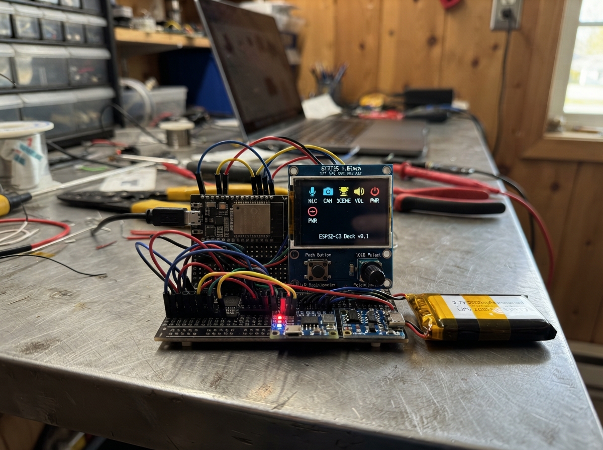
Build a portable stream deck powered by an ESP32-C3 that sends customizable keyboard commands via Bluetooth. This compact controller features a 1.8-inch color display, 12 programmable buttons, and 3 analog knobs for controlling streaming software, music players, or any application that accepts keyboard input.
This guide provides a complete wiring diagram, full parts list, and step-by-step assembly instructions to build the rechargeable power system, integrate the display and input controls, and load the firmware. Makers will have a fully functional wireless macro pad ready for streaming, content creation, or general productivity tasks.
Wiring diagram

Gather all the parts
Assemble it in 7 steps
1. Build the rechargeable power section
With nothing plugged in, connect battery BAT+ to charger B+ (battery positive), and battery BAT- to charger B- (battery ground). Connect charger OUT+ to regulator VIN (battery power), and charger OUT- to regulator GND (ground). Connect regulator VOUT to the ESP32-C3 DevKitM-1 3V3 pin (regulated power). Also connect regulator GND to an ESP32-C3 DevKitM-1 GND pin (ground). The 3V3 and GND rails now power the screen, switches, knob reader, and knobs.
- Use red wire for every positive connection and black wire for every ground connection.
- The regulator may be left enabled by leaving its optional SHDN pin disconnected.
- Never connect the battery, charger OUT+, or regulator VIN directly to the ESP32-C3 DevKitM-1 3V3 pin — their voltage changes with battery charge and can damage the board.
- Make sure the battery's red and black leads are not swapped — reversed battery wiring can damage the charger and battery.
2. Add the USB charging lead
Connect the TP4056 charger IN+ to the positive wire of a 5 V USB charging lead (charging power), and IN- to its ground wire (ground). This USB lead is only for charging the battery; it does not connect to the ESP32-C3 DevKitM-1 USB port.
- Use a TP4056 module marked with B+, B-, OUT+, and OUT- pads; that version includes battery protection.
- Charge from a normal 5 V USB power source.
- Do not connect the charger IN pads to the regulated 3.3 V rail — the charger needs 5 V USB input to charge correctly.
- Do not charge a swollen, punctured, hot, or unprotected battery — it can catch fire.
3. Wire the small screen
Connect TFT VCC to 3V3 (power), TFT GND to GND (ground), TFT SCK or CLK to GPIO4 (clock), TFT MOSI or SDA/DIN to GPIO6 (data), TFT CS to GPIO7 (screen select), and TFT DC or A0 to GPIO3 (data/command). Connect TFT RST and BLK to 3V3 so the screen resets and its light stays on.
- Some screens label the SPI clock SCL and the data pin SDA; these labels mean SCK and MOSI here.
- GPIO4 and GPIO6 are shared later with the knob reader; that is intentional.
- Make sure VCC and GND are not swapped — swapped power can damage the screen.
4. Wire the 12 key switches
Connect MCP23017 VDD to 3V3 (power), VSS to GND (ground), SDA to GPIO0 (data), and SCL to GPIO1 (clock). For each Outemu switch, connect one contact to GND (ground). Connect the other contact of keys 1 through 8 to MCP23017 GPA0 through GPA7 in order (signal), then keys 9 through 12 to GPB0 through GPB3 (signal).
- An Outemu switch has two pairs of legs; use one leg from each opposing pair, not two legs on the same side.
- The code provides the needed pull-up resistors, so no extra resistors are needed.
- Keep each switch on its own MCP23017 pin; joining two signal wires makes two switches act like the same key.
5. Wire the knob reader
Connect MCP3008 VDD and VREF to 3V3 (power), and both AGND and DGND to GND (ground). Connect CLK to GPIO4 (clock), DIN to GPIO6 (data to the reader), DOUT to GPIO5 (data from the reader), and CS/SHDN to GPIO10 (reader select). GPIO4 and GPIO6 are intentionally shared with the screen; GPIO7 and GPIO10 keep the two modules separate.
- Keep these wires short and match the printed labels carefully; DOUT and DIN have similar names but are not interchangeable.
- GPIO5 only carries data from the MCP3008 back to the ESP32-C3.
- Do not feed a knob signal directly into the ESP32-C3 DevKitM-1 in this build — it must go to the MCP3008.
6. Connect the three knobs
For each 10 kΩ potentiometer, connect one outside leg to 3V3 (power), the other outside leg to GND (ground), and its center leg to its MCP3008 input: knob 1 to CH0 (signal), knob 2 to CH1 (signal), and knob 3 to CH2 (signal).
- The center leg is normally the middle solder lug or middle row of pins.
- If clockwise turning works backwards, swap only that knob's two outside wires.
- All three outside knob connections must use 3V3, not 5 V — 5 V can damage the MCP3008.
7. Inspect, charge, and use the deck
Inspect every wire, especially the battery, regulator, and shared ground connections. Charge through the TP4056 USB input before first portable use. Then unplug the charging lead and turn on the Stream Deck by connecting the battery; the display and controls are powered from the regulated 3.3 V supply. Use the ESP32-C3 DevKitM-1 USB port when you need to press Deploy in Schematik or want USB power while developing.
- This 2000 mAh battery is estimated to run the deck for about 8 hours; screen brightness and Bluetooth activity affect the real time.
- Use a small enclosure or strain relief so the battery wires cannot be pulled loose.
- Never leave LiPo charging unattended or charge it on fabric, paper, or another flammable surface.
- Unplug power before moving wires — a loose wire can touch the wrong pin and damage a module.
Review all connections
1. Connections between "io_expander" and "ESP32"
2. Connections between "tft" and "ESP32"
3. Connections between "adc" and "ESP32"
4. Connections between "pot1" and "ESP32"
5. Connections between "pot2" and "ESP32"
6. Connections between "pot3" and "ESP32"
7. Connections between "key1" and "ESP32"
8. Connections between "key2" and "ESP32"
9. Connections between "key3" and "ESP32"
10. Connections between "key4" and "ESP32"
11. Connections between "key5" and "ESP32"
12. Connections between "key6" and "ESP32"
13. Connections between "key7" and "ESP32"
14. Connections between "key8" and "ESP32"
15. Connections between "key9" and "ESP32"
16. Connections between "key10" and "ESP32"
17. Connections between "key11" and "ESP32"
18. Connections between "key12" and "ESP32"
19. Connections between "battery" and "ESP32"
20. Connections between "charger" and "ESP32"
21. Connections between "regulator" and "ESP32"
Deploy the firmware
#include <Arduino.h>
#include <Wire.h>
#include <SPI.h>
#include <Adafruit_GFX.h>
#include <Adafruit_ST7735.h>
#include <Adafruit_MCP23X17.h>
#include <BleKeyboard.h>


// Forward declarations
uint16_t readMcp3008(uint8_t channel);
void drawStaticScreen();
void drawStatus(const char *text);
void showStatus(const char *text);
uint8_t functionKeyFor(uint8_t index);
void sendKey(uint8_t keycode, const char *label);
void scanKeys();
void scanPots();

constexpr uint8_t I2C_SDA_PIN = 0;
constexpr uint8_t I2C_SCL_PIN = 1;
constexpr uint8_t SPI_SCK_PIN = 4;
constexpr uint8_t SPI_MISO_PIN = 5;
constexpr uint8_t SPI_MOSI_PIN = 6;
constexpr uint8_t TFT_CS_PIN = 7;
constexpr uint8_t TFT_DC_PIN = 3;
constexpr uint8_t ADC_CS_PIN = 10;
constexpr uint8_t KEY_COUNT = 12;
constexpr uint8_t POT_COUNT = 3;
constexpr uint16_t POT_DEADBAND = 18;
constexpr uint32_t DEBOUNCE_MS = 28;
constexpr uint32_t STATUS_HOLD_MS = 1400;

Adafruit_ST7735 tft(TFT_CS_PIN, TFT_DC_PIN, -1);
Adafruit_MCP23X17 mcp;
BleKeyboard bleKeyboard("C3 Stream Deck", "Schematik", 100);

bool stableKeyState[KEY_COUNT];
bool lastRawKeyState[KEY_COUNT];
uint32_t keyChangedAt[KEY_COUNT];
uint16_t potValue[POT_COUNT];
uint32_t statusUntil = 0;
char statusText[28] = "Starting...";

uint16_t readMcp3008(uint8_t channel) {
  SPI.beginTransaction(SPISettings(1350000, MSBFIRST, SPI_MODE0));
  digitalWrite(ADC_CS_PIN, LOW);
  SPI.transfer(0x01);
  uint8_t highByte = SPI.transfer(static_cast<uint8_t>((0x08 | channel) << 4));
  uint8_t lowByte = SPI.transfer(0x00);
  digitalWrite(ADC_CS_PIN, HIGH);
  SPI.endTransaction();
  return static_cast<uint16_t>(((highByte & 0x03) << 8) | lowByte);
}

void drawStaticScreen() {
  tft.fillScreen(ST77XX_BLACK);
  tft.setTextWrap(false);
  tft.setTextSize(1);
  tft.setTextColor(ST77XX_CYAN);
  tft.setCursor(8, 8);
  tft.print("C3 STREAM DECK");
  tft.drawFastHLine(6, 20, 116, ST77XX_BLUE);
  tft.setTextColor(ST77XX_WHITE);
  tft.setCursor(8, 30);
  tft.print("Bluetooth: ");
  tft.print(bleKeyboard.isConnected() ? "CONNECTED" : "PAIR ME");
  tft.setCursor(8, 48);
  tft.print("Keys: F13 - F24");
  tft.setCursor(8, 66);
  tft.print("Knobs: F1 - F6");
  tft.drawRect(6, 92, 116, 42, ST77XX_BLUE);
}

void drawStatus(const char *text) {
  tft.fillRect(8, 95, 112, 36, ST77XX_BLACK);
  tft.setTextSize(1);
  tft.setTextColor(ST77XX_YELLOW);
  tft.setCursor(12, 103);
  tft.print(text);
}

void showStatus(const char *text) {
  strncpy(statusText, text, sizeof(statusText) - 1);
  statusText[sizeof(statusText) - 1] = '\0';
  drawStatus(statusText);
  statusUntil = millis() + STATUS_HOLD_MS;
}

uint8_t functionKeyFor(uint8_t index) {
  return static_cast<uint8_t>(KEY_F13 + index);
}

void sendKey(uint8_t keycode, const char *label) {
  if (bleKeyboard.isConnected()) {
    bleKeyboard.write(keycode);
    showStatus(label);
  } else {
    showStatus("Pair Bluetooth first");
  }
}

void scanKeys() {
  uint32_t now = millis();
  for (uint8_t i = 0; i < KEY_COUNT; ++i) {
    bool rawPressed = !mcp.digitalRead(i);
    if (rawPressed != lastRawKeyState[i]) {
      lastRawKeyState[i] = rawPressed;
      keyChangedAt[i] = now;
    }
    if (rawPressed != stableKeyState[i] && now - keyChangedAt[i] >= DEBOUNCE_MS) {
      stableKeyState[i] = rawPressed;
      if (stableKeyState[i]) {
        char label[24];
        snprintf(label, sizeof(label), "Key %u: F%u", i + 1, i + 13);
        sendKey(functionKeyFor(i), label);
      }
    }
  }
}

void scanPots() {
  for (uint8_t i = 0; i < POT_COUNT; ++i) {
    uint16_t value = readMcp3008(i);
    int32_t difference = static_cast<int32_t>(value) - static_cast<int32_t>(potValue[i]);
    if (abs(difference) >= POT_DEADBAND) {
      potValue[i] = value;
      uint8_t lowerKey = KEY_F1 + (i * 2);
      uint8_t keyToSend = difference > 0 ? lowerKey + 1 : lowerKey;
      char label[24];
      snprintf(label, sizeof(label), "Knob %u: F%u", i + 1, keyToSend - KEY_F1 + 1);
      sendKey(keyToSend, label);
    }
  }
}

void setup() {
  pinMode(ADC_CS_PIN, OUTPUT);
  digitalWrite(ADC_CS_PIN, HIGH);
  Wire.begin(I2C_SDA_PIN, I2C_SCL_PIN);
  SPI.begin(SPI_SCK_PIN, SPI_MISO_PIN, SPI_MOSI_PIN, TFT_CS_PIN);

  tft.initR(INITR_BLACKTAB);
  tft.setRotation(1);
  tft.fillScreen(ST77XX_BLACK);

  if (!mcp.begin_I2C(0x20, &Wire)) {
    drawStatus("MCP23017 not found");
    while (true) { delay(100); }
  }
  for (uint8_t i = 0; i < KEY_COUNT; ++i) {
    mcp.pinMode(i, INPUT_PULLUP);
    stableKeyState[i] = !mcp.digitalRead(i);
    lastRawKeyState[i] = stableKeyState[i];
    keyChangedAt[i] = millis();
  }
  for (uint8_t i = 0; i < POT_COUNT; ++i) {
    potValue[i] = readMcp3008(i);
  }
  bleKeyboard.begin();
  drawStaticScreen();
  drawStatus("Ready to pair");
}

void loop() {
  static bool wasConnected = false;
  bool connected = bleKeyboard.isConnected();
  if (connected != wasConnected) {
    wasConnected = connected;
    drawStaticScreen();
    showStatus(connected ? "Bluetooth connected" : "Pair Bluetooth first");
  }
  scanKeys();
  scanPots();
  if (statusUntil != 0 && millis() > statusUntil) {
    drawStatus(connected ? "Ready" : "Pair Bluetooth first");
    statusUntil = 0;
  }
  delay(4);
}
Remix this project
Make it yours in one click
Open a full copy of this project in your own Schematik workspace — diagram, code, parts, and assembly steps included. Swap the sensor, add features, or redesign the whole thing with AI. The author's original stays untouched.