Community project
Authorized Network Diagnostic Tool
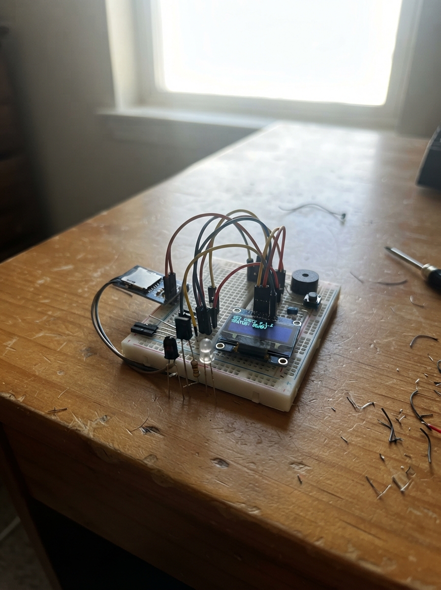
This project builds a portable network diagnostic tool on an ESP32 microcontroller with a menu-driven interface for authorized testing and analysis. The device combines WiFi scanning, infrared protocol detection, and local data logging into a single handheld unit, making it useful for network professionals and makers who need to inspect wireless environments and capture IR signals in the field.
The guide provides a complete parts list, wiring diagram, and step-by-step assembly instructions starting with power rails and the OLED display, then adding navigation buttons, audio feedback, storage, and infrared capabilities. Firmware is included to run the diagnostic interface with pages for WiFi enumeration, IR tools, SD card management, and system information—all controlled through seven push buttons and displayed on a 128×64 monochrome OLED screen.
Wiring diagram

Gather all the parts
Assemble it in 8 steps
1. Inspect every part before applying power
Read the labels printed beside the ESP32 header holes and match them to the board image: use only GPIO1 through GPIO16 named in the wiring table. On the OLED, identify VCC, GND, SDA, and SCL. On the SD board photo, the header is labelled CS, SCK, MOSI, MISO, VCC, and GND; do not assume header order—follow its printed text. For a bare VS1838B, face the rounded dark lens toward you and verify its lead order from its own seller drawing before wiring; different look-alike parts can have different lead order. The IR LED has a long anode lead and a shorter cathode lead beside a flat edge. Put each tactile switch across the breadboard centre gap: the two legs on one side are already joined internally, and pressing joins that side to the opposite pair.
- VERIFY BEFORE POWERING: check the VS1838B lead order from its packaging, listing, or markings before connecting it.
- A passive piezo has no meaningful polarity; an active buzzer may have a plus sign. This project is safe only for a piezo or an active buzzer drawing no more than 12 mA.
- Do not connect a pin labelled 5V on the SD module to an ESP32 GPIO or to the 3.3 V rail.
- Do not power the breadboard from both ESP32 5 V and 3.3 V pins at once.
2. Make the 3.3 V and ground rails
Place the ESP32 so its two header rows straddle the breadboard centre channel. Plug the USB-C cable from the power bank into the board's USB connector. Use one jumper from an ESP32 3V3 header pin to the red breadboard rail and one jumper from ESP32 GND to the blue breadboard rail. If either rail is split in the middle, bridge its two halves with short jumpers. Do not connect the ESP32 5V header pin to these rails.
- Use red wires for 3.3 V and black wires for ground consistently.
- The USB cable powers the board; the breadboard rail is only its regulated 3.3 V output.
- Do not join the red 3.3 V rail to the blue ground rail; this creates a short and can reset or damage the board.
3. Wire and test the OLED first
Solder the four supplied header pins to the OLED if needed. Connect OLED VCC to the 3.3 V rail (power), OLED GND to the ground rail (ground), OLED SDA to GPIO8 (data), and OLED SCL to GPIO9 (clock). Place the 100 nF ceramic capacitor across the nearby 3.3 V and ground rows; this capacitor has no polarity. After deploying the project, the screen should briefly show CYBERCORE v1 and DISPLAY OK.
- If the screen is blank, switch off USB power before checking that SDA and SCL are not swapped.
- This design assumes the usual OLED address 0x3C; some modules instead use 0x3D.
- Keep OLED VCC and GND correct—swapped power can damage the display.
4. Add the seven menu buttons
Put each 6×6 mm tactile switch across the breadboard centre gap so it does not short its own two internally joined legs. For every button, connect one side to the ground rail. Connect the opposite side respectively to GPIO1 for UP, GPIO2 for DOWN, GPIO3 for LEFT, GPIO4 for RIGHT, GPIO5 for SELECT, GPIO6 for BACK, and GPIO7 for POWER/WAKE. The firmware enables internal pull-ups, so no external pull-up resistors are needed: an unpressed button reads high and a pressed button reads ground.
- Add and test one switch at a time; a button should cause one menu movement per press.
- The spare eighth switch stays disconnected.
- A tactile switch rotated by 90 degrees can permanently connect a GPIO to ground; always straddle the breadboard centre gap.
5. Add the buzzer
For a verified passive piezo buzzer, connect one lead to GPIO16 (signal) and the other lead to the ground rail (ground). Pressing a button produces a short tone. If the part is an active electromagnetic buzzer or its label specifies more than 12 mA, do not connect it directly: a transistor driver is required and is not in the listed parts.
- A passive piezo normally sounds only when driven with a changing signal; an active buzzer often sounds steadily from DC power.
- A plus mark identifies the preferred positive lead on a polarized active buzzer, but it does not prove its current is GPIO-safe.
- Do not drive an unknown high-current buzzer from GPIO16; excess current can damage the ESP32 output.
6. Add the MicroSD module on 3.3 V
With USB power unplugged, insert the MicroSD module. Connect VCC to the 3.3 V rail (power), GND to ground (ground), CS to GPIO10 (select), MOSI to GPIO11 (data to card), SCK to GPIO12 (clock), and MISO to GPIO13 (data from card). Place the 100 nF ceramic capacitor and the 10 µF electrolytic across the SD power rows. The electrolytic capacitor long positive lead goes to 3.3 V; its striped negative lead goes to ground. Insert the FAT32-formatted 4 GB card, then reconnect USB power.
- This photographed module uses a 74HC125 buffer and regulator. Supplying its VCC at 3.3 V keeps its logic outputs—including MISO—at a safe 3.3 V level.
- Use the SD Card menu and SELECT to write and read cybercore_test.txt.
- Do not power this module from 5 V for this project: some 5 V SD modules can output 5 V on MISO and harm a 3.3 V ESP32 pin.
- Do not insert or remove the card while writing a file.
7. Add the IR receiver and safe IR transmitter
After confirming the VS1838B lead order, connect its VCC to 3.3 V (power), GND to ground (ground), and OUT to GPIO14 (signal). Place the 100 nF ceramic capacitor directly across its VCC and GND rows; it has no polarity. For the IR transmitter, connect GPIO15 to one end of the 220 ohm resistor (current limiting), the resistor's other end to the IR LED long anode lead, and the short cathode lead to ground. The 220 ohm resistor keeps typical LED current near 8–10 mA from a 3.3 V GPIO.
- An IR LED light is invisible to eyes; view it through a phone camera while the IR Tools test sends its short burst.
- The IR receiver output remains ESP32-safe only when its VCC is 3.3 V.
- Never connect the bare IR LED directly to GPIO15; without the 220 ohm resistor it can draw damaging current.
- Do not rely on lead position alone for the IR receiver; verify its exact VCC/GND/OUT order first.
8. Run the complete diagnostic interface
Reconnect USB power, then press Deploy in Schematik. The start screen shows CYBERCORE v1. Use UP and DOWN to select a menu item, SELECT to enter it, and BACK to return. In Wi-Fi Scanner, SELECT starts a passive scan; UP and DOWN browse results, SELECT opens details, and RIGHT saves the current results to wifi_scan.csv when SD is ready. Scan only networks you own or are authorized to assess.
- The POWER/WAKE button wakes the user interface; it is not a battery switch.
- Serial output at 115200 baud reports SD state, scan count, and decoded IR values.
- The Wi-Fi feature lists nearby beacon information only; do not use this device to interfere with networks or devices you do not control.
Review all connections
1. Connections between "oled_1" and "ESP32"
2. Connections between "sd_module_1" and "ESP32"
3. Connections between "ir_receiver_1" and "ESP32"
4. Connections between "ir_led_resistor_1" and "ESP32"
5. Connections between "ir_led_1" and "ESP32"
6. Connections between "buzzer_1" and "ESP32"
7. Connections between "button_up" and "ESP32"
8. Connections between "button_down" and "ESP32"
9. Connections between "button_left" and "ESP32"
10. Connections between "button_right" and "ESP32"
11. Connections between "button_select" and "ESP32"
12. Connections between "button_back" and "ESP32"
13. Connections between "button_wake" and "ESP32"
14. Connections between "cap_oled_100n" and "ESP32"
15. Connections between "cap_sd_100n" and "ESP32"
16. Connections between "cap_ir_100n" and "ESP32"
17. Connections between "cap_sd_10u" and "ESP32"
Deploy the firmware
#include <Arduino.h>
#include <Wire.h>
#include <SPI.h>
#include <SD.h>
#include <WiFi.h>
#include <Adafruit_GFX.h>
#include <Adafruit_SH110X.h>
#include <IRremote.hpp>

// CYBERCORE v1: passive diagnostics for networks you own or are authorized to test.

struct Button { uint8_t pin; bool previous; uint32_t lastChange; };

enum ButtonId { UP, DOWN, LEFT, RIGHT, SELECT, BACK, WAKE, NONE };

enum Page { HOME, WIFI_LIST, WIFI_DETAIL, IR_TOOLS, SD_CARD, SYSTEM_INFO, SETTINGS };


// Forward declarations
void toneBeep(uint16_t frequency, uint16_t duration);
ButtonId readButton();
void printLine(const String &text, int y);
void header(const char *title);
void drawHome();
void scanWiFi();
void drawWiFiList();
void drawWiFiDetail();
void drawIrTools();
void drawSD();
void drawSystem();
void drawSettings();
void drawPage();
void logScan();
void writeSdTest();
void handleButton(ButtonId b);
int networkChannel(int index);
String networkBssid(int index);
const char *irProtocolName(uint8_t protocol);

constexpr uint8_t BTN_UP = 1;
constexpr uint8_t BTN_DOWN = 2;
constexpr uint8_t BTN_LEFT = 3;
constexpr uint8_t BTN_RIGHT = 4;
constexpr uint8_t BTN_SELECT = 5;
constexpr uint8_t BTN_BACK = 6;
constexpr uint8_t BTN_WAKE = 7;
constexpr uint8_t OLED_SDA = 8;
constexpr uint8_t OLED_SCL = 9;
constexpr uint8_t SD_CS = 10;
constexpr uint8_t SD_MOSI = 11;
constexpr uint8_t SD_SCK = 12;
constexpr uint8_t SD_MISO = 13;
constexpr uint8_t IR_RX_PIN = 14;
constexpr uint8_t IR_TX_PIN = 15;
constexpr uint8_t BUZZER_PIN = 16;
constexpr uint8_t OLED_ADDR = 0x3C;
constexpr uint8_t SCREEN_W = 128;
constexpr uint8_t SCREEN_H = 64;
constexpr uint16_t DEBOUNCE_MS = 35;
constexpr uint16_t MAX_NETWORKS = 30;

Adafruit_SH1106G display(SCREEN_W, SCREEN_H, &Wire, -1);


Button buttons[] = {
  {BTN_UP, HIGH, 0}, {BTN_DOWN, HIGH, 0}, {BTN_LEFT, HIGH, 0},
  {BTN_RIGHT, HIGH, 0}, {BTN_SELECT, HIGH, 0}, {BTN_BACK, HIGH, 0}, {BTN_WAKE, HIGH, 0}
};


Page page = HOME;
int menuIndex = 0;
int selectedNetwork = 0;
int networkCount = 0;
bool sdReady = false;
bool screenSleeping = false;
String statusLine = "Ready";

const char *menuItems[] = {"Wi-Fi Scanner", "IR Tools", "SD Card", "System Info", "Settings"};
constexpr int MENU_COUNT = sizeof(menuItems) / sizeof(menuItems[0]);

void toneBeep(uint16_t frequency = 1800, uint16_t duration = 45) {
  // Safe for a passive piezo. If your part is an electromagnetic buzzer or draws >12 mA, disconnect it and add a transistor driver.
  ledcAttach(BUZZER_PIN, frequency, 8);
  ledcWriteTone(BUZZER_PIN, frequency);
  delay(duration);
  ledcWriteTone(BUZZER_PIN, 0);
}

ButtonId readButton() {
  for (uint8_t i = 0; i < sizeof(buttons) / sizeof(buttons[0]); i++) {
    bool now = digitalRead(buttons[i].pin);
    if (now != buttons[i].previous && millis() - buttons[i].lastChange > DEBOUNCE_MS) {
      buttons[i].previous = now;
      buttons[i].lastChange = millis();
      if (now == LOW) return static_cast<ButtonId>(i);
    }
  }
  return NONE;
}

const char *encryptionName(int mode) {
  // ESP-IDF Wi-Fi authentication enum values are stable; numeric cases also
  // keep this passive scanner compatible with the browser Wi-Fi facade.
  switch (static_cast<int>(mode)) {
    case 0: return "Open";
    case 1: return "WEP";
    case 2: return "WPA";
    case 3: return "WPA2";
    case 4: return "WPA/WPA2";
    case 5: return "WPA2 Ent";
    case 6: return "WPA3";
    case 7: return "WPA2/WPA3";
    default: return "Unknown";
  }
}

int networkChannel(int index) {
#if defined(__EMSCRIPTEN__)
  (void)index;
  return WiFi.channel();
#else
  return WiFi.channel(index);
#endif
}

String networkBssid(int index) {
#if defined(__EMSCRIPTEN__)
  (void)index;
  return "simulated";
#else
  return WiFi.BSSIDstr(index);
#endif
}

const char *irProtocolName(uint8_t protocol) {
  // Numeric protocol is portable across IRremote builds; real hardware still
  // reports address and command over Serial for remote identification.
  switch (protocol) {
    case 1: return "Pulse";
    case 2: return "NEC";
    default: return "IR signal";
  }
}

void printLine(const String &text, int y) { display.setCursor(0, y); display.print(text); }
void header(const char *title) { display.clearDisplay(); display.setTextSize(1); display.setTextColor(SH110X_WHITE); printLine("CYBERCORE v1", 0); printLine(title, 10); display.drawFastHLine(0, 20, 128, SH110X_WHITE); }

void drawHome() {
  header("Main menu");
  for (int i = 0; i < MENU_COUNT; i++) {
    int y = 24 + i * 8;
    if (i == menuIndex) { display.fillRect(0, y - 1, 128, 8, SH110X_WHITE); display.setTextColor(SH110X_BLACK); }
    else display.setTextColor(SH110X_WHITE);
    printLine(String(i == menuIndex ? "> " : "  ") + menuItems[i], y);
  }
  display.setTextColor(SH110X_WHITE); display.display();
}

void scanWiFi() {
  statusLine = "Scanning...";
  header("Wi-Fi scanner"); printLine("Scanning authorized", 27); printLine("networks...", 37); display.display();
  WiFi.mode(WIFI_STA);
  WiFi.disconnect();
  delay(100);
  networkCount = WiFi.scanNetworks(false, true);
  if (networkCount < 0) networkCount = 0;
  if (networkCount > MAX_NETWORKS) networkCount = MAX_NETWORKS;
  selectedNetwork = 0;
  statusLine = String(networkCount) + " network(s) found";
  Serial.println(statusLine);
}

void drawWiFiList() {
  header("Wi-Fi scanner");
  if (networkCount == 0) { printLine("No results. SELECT", 28); printLine("starts a new scan.", 38); display.display(); return; }
  int first = max(0, selectedNetwork - 2);
  for (int row = 0; row < 5 && first + row < networkCount; row++) {
    int index = first + row, y = 23 + row * 8;
    if (index == selectedNetwork) { display.fillRect(0, y - 1, 128, 8, SH110X_WHITE); display.setTextColor(SH110X_BLACK); }
    else display.setTextColor(SH110X_WHITE);
    String ssid = WiFi.SSID(index); if (ssid.length() == 0) ssid = "<hidden>";
    if (ssid.length() > 14) ssid = ssid.substring(0, 14);
    printLine(String(index == selectedNetwork ? ">" : " ") + ssid + " " + String(WiFi.RSSI(index)), y);
  }
  display.setTextColor(SH110X_WHITE); display.display();
}

void drawWiFiDetail() {
  header("Network detail");
  if (networkCount == 0) { printLine("No scan results", 28); display.display(); return; }
  String ssid = WiFi.SSID(selectedNetwork); if (ssid.length() == 0) ssid = "<hidden>";
  printLine(ssid.substring(0, 20), 24);
  printLine("RSSI: " + String(WiFi.RSSI(selectedNetwork)) + " dBm", 33);
  printLine("Channel: " + String(networkChannel(selectedNetwork)), 42);
  printLine(String(encryptionName(WiFi.encryptionType(selectedNetwork))), 51);
  printLine(networkBssid(selectedNetwork), 60);
  display.display();
}

void drawIrTools() { header("IR tools"); printLine("Receiver ready", 27); printLine("SELECT: send safe", 37); printLine("38 kHz test burst", 47); printLine("BACK: menu", 57); display.display(); }
void drawSD() { header("SD card"); printLine(sdReady ? "SD OK" : "SD not detected", 28); printLine("SELECT: write test", 38); printLine(statusLine.substring(0, 21), 52); display.display(); }
void drawSystem() { header("System info"); printLine("Chip: ESP32-S3", 26); printLine("Flash: " + String(ESP.getFlashChipSize() / 1048576) + " MB", 35); printLine("PSRAM: " + String(ESP.getPsramSize() / 1048576) + " MB", 44); printLine("Heap: " + String(ESP.getFreeHeap() / 1024) + " KB", 53); display.display(); }
void drawSettings() { header("Settings"); printLine("USB powered", 28); printLine("Wake button wakes", 38); printLine("the display", 48); display.display(); }
void drawPage() { if (screenSleeping) return; switch(page) { case HOME: drawHome(); break; case WIFI_LIST: drawWiFiList(); break; case WIFI_DETAIL: drawWiFiDetail(); break; case IR_TOOLS: drawIrTools(); break; case SD_CARD: drawSD(); break; case SYSTEM_INFO: drawSystem(); break; case SETTINGS: drawSettings(); break; } }

void logScan() {
  if (!sdReady) { statusLine = "SD not detected"; return; }
  File log = SD.open("/wifi_scan.csv", FILE_WRITE);
  if (!log) { statusLine = "Log open failed"; return; }
  log.println("scan_ms,ssid,rssi_dbm,channel,security,bssid");
  for (int i = 0; i < networkCount; i++) {
    String ssid = WiFi.SSID(i); ssid.replace(",", " ");
    log.printf("%lu,%s,%d,%d,%s,%s\n", millis(), ssid.c_str(), WiFi.RSSI(i), networkChannel(i), encryptionName(WiFi.encryptionType(i)), networkBssid(i).c_str());
  }
  log.close(); statusLine = "Saved wifi_scan.csv"; Serial.println(statusLine);
}

void writeSdTest() {
  if (!sdReady) { statusLine = "SD not detected"; return; }
  File test = SD.open("/cybercore_test.txt", FILE_WRITE);
  if (!test) { statusLine = "Test file failed"; return; }
  test.println("CYBERCORE v1 SD test OK"); test.close();
  test = SD.open("/cybercore_test.txt", FILE_READ);
  statusLine = test ? "SD OK: readback OK" : "Readback failed";
  if (test) test.close(); Serial.println(statusLine);
}

void handleButton(ButtonId b) {
  if (b == NONE) return;
  if (screenSleeping) { screenSleeping = false; toneBeep(); drawPage(); return; }
  toneBeep();
  if (b == WAKE) { statusLine = "Display awake"; drawPage(); return; }
  if (page == HOME) {
    if (b == UP && menuIndex > 0) menuIndex--;
    else if (b == DOWN && menuIndex < MENU_COUNT - 1) menuIndex++;
    else if (b == SELECT) { page = static_cast<Page>(menuIndex + 1); if (page == WIFI_LIST) scanWiFi(); }
  } else if (page == WIFI_LIST) {
    if (b == UP && selectedNetwork > 0) selectedNetwork--;
    else if (b == DOWN && selectedNetwork < networkCount - 1) selectedNetwork++;
    else if (b == SELECT) { if (networkCount) page = WIFI_DETAIL; else scanWiFi(); }
    else if (b == RIGHT) logScan();
    else if (b == BACK) page = HOME;
  } else if (page == WIFI_DETAIL) { if (b == BACK) page = WIFI_LIST; }
  else if (page == IR_TOOLS) { if (b == SELECT) { IrSender.begin(IR_TX_PIN); IrSender.sendNEC(0x00, 0x00, 0); statusLine = "IR NEC test sent"; } else if (b == BACK) page = HOME; }
  else if (page == SD_CARD) { if (b == SELECT) writeSdTest(); else if (b == BACK) page = HOME; }
  else { if (b == BACK) page = HOME; }
  drawPage();
}

void setup() {
  Serial.begin(115200); delay(300); Serial.println("CYBERCORE v1 boot");
  for (auto &button : buttons) pinMode(button.pin, INPUT_PULLUP);
  pinMode(BUZZER_PIN, OUTPUT);
  Wire.begin(OLED_SDA, OLED_SCL);
  if (!display.begin(OLED_ADDR, true)) { Serial.println("OLED initialization failed"); while (true) delay(100); }
  display.clearDisplay(); printLine("CYBERCORE v1", 20); printLine("DISPLAY OK", 36); display.display(); delay(1000);
  SPI.begin(SD_SCK, SD_MISO, SD_MOSI, SD_CS);
  sdReady = SD.begin(SD_CS, SPI, 10000000);
  Serial.println(sdReady ? "SD OK" : "SD initialization failed");
  IrReceiver.begin(IR_RX_PIN, DISABLE_LED_FEEDBACK);
  drawPage();
}

void loop() {
  ButtonId button = readButton(); handleButton(button);
  if (IrReceiver.decode()) {
    Serial.print("IR protocol: "); Serial.print(irProtocolName(static_cast<uint8_t>(IrReceiver.decodedIRData.protocol)));
    Serial.print(" address: 0x"); Serial.print(IrReceiver.decodedIRData.address, HEX);
    Serial.print(" command: 0x"); Serial.println(IrReceiver.decodedIRData.command, HEX);
    statusLine = "IR " + String(irProtocolName(static_cast<uint8_t>(IrReceiver.decodedIRData.protocol)));
    if (page == IR_TOOLS) drawPage();
    IrReceiver.resume();
  }
}
Remix this project
Make it yours in one click
Open a full copy of this project in your own Schematik workspace — diagram, code, parts, and assembly steps included. Swap the sensor, add features, or redesign the whole thing with AI. The author's original stays untouched.