Community project
Autonomous Fault-Safe Irrigation
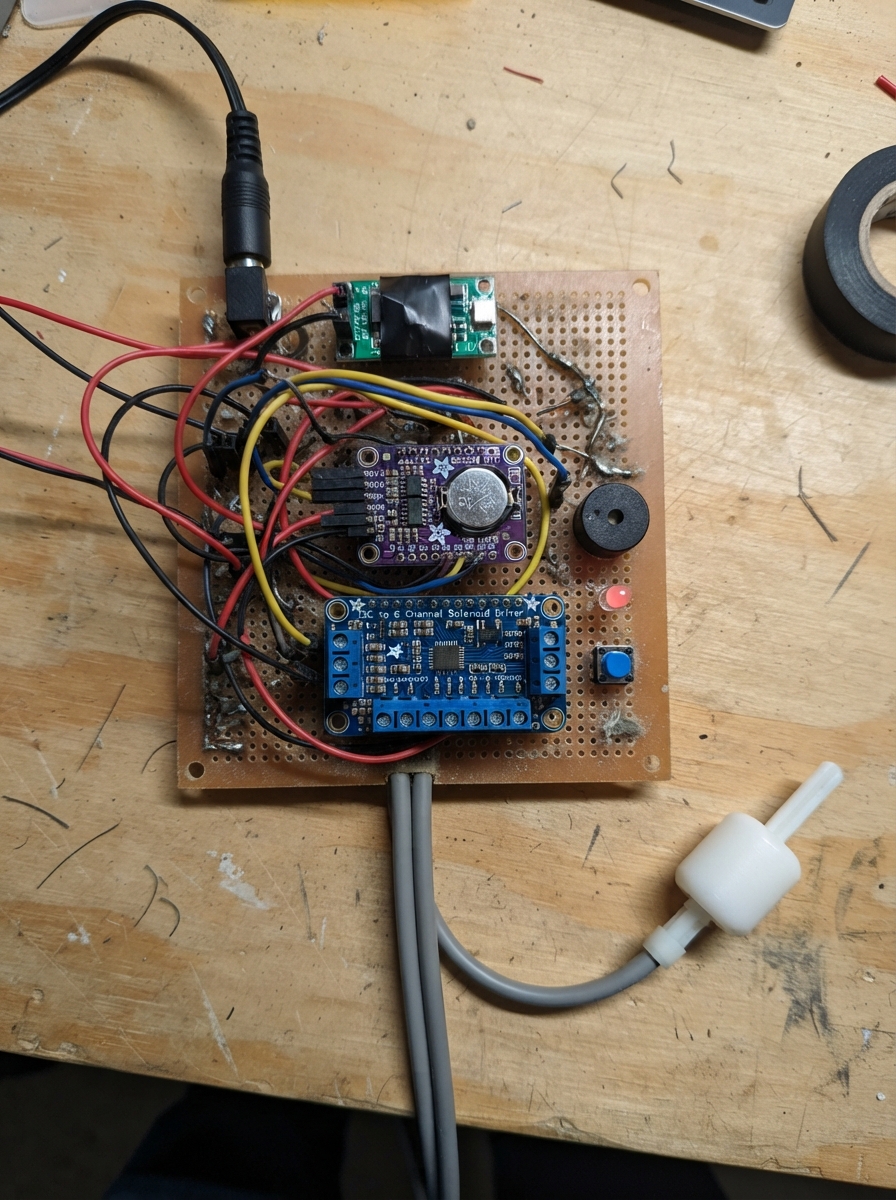
This project builds a fault-safe irrigation controller that manages up to four independent watering zones on a schedule, with real-time flow monitoring and automatic shutoff if a line breaks or clogs. The system uses an ESP32 microcontroller, a precision real-time clock for reliable scheduling, an I2C solenoid driver to control four 12V irrigation valves, and flow sensors in each zone to detect problems before water is wasted.
The guide provides a complete wiring diagram, parts list, and step-by-step assembly instructions for mounting the controller in a weatherproof box and connecting the four branch lines with flow meters. Firmware is included that learns the normal flow rate for each zone during setup, monitors for faults during operation, sounds an alarm if flow drops unexpectedly, and allows manual override via push buttons. A web interface lets you set schedules, view flow data, and respond to rain sensor input to skip watering after rainfall.
Wiring diagram
Gather all the parts
Assemble it in 7 steps
1. Choose the valves and make the four branch lines
Leave the 2-inch GI main line alone. After its filter, make four smaller irrigation branches, each with a manual isolation tap, then install valve_1 through valve_4 in the direction marked by their arrows. Each valve must be a 12 V DC, normally-closed, direct-acting valve specified to open at zero differential pressure; ordinary irrigation diaphragm valves may not open from your low overhead-tank pressure.
- Put the valves after a cleanable filter so grit cannot hold a valve open.
- Use unions on both sides of every valve so it can be removed for cleaning.
- Do not buy a pilot-operated valve that needs pressure difference — it can stay shut with gravity water even when the controller commands it on.
2. Install one meter in each zone
Fit flow_1, flow_2, flow_3, and flow_4 downstream of their matching valve, with the moulded arrow pointing toward the drip lines. Keep enough straight pipe before each meter for the maker’s instructions, then connect the meter’s VCC → 5V (power), GND → GND (ground), and SIGNAL → its listed ESP32 signal wire.
- Put the meter where you can reach its small filter and where a leak before the meter cannot hide from the fault check.
- Do not power a flow-meter signal wire from 5 V — the signal is pulled up safely to 3.3 V by the controller; putting 5 V onto an ESP32 input can damage it.
3. Prepare the weatherproof controller box
Mount the ESP32, rtc, solenoid_driver, buck_5v, valve_fuse, status_green, status_red, alert_buzzer, and four zone buttons inside a UV-resistant IP65 enclosure. Use downward-facing cable glands for every field cable and make drip loops below the glands so rain cannot run into the box. Fit the CR1220 coin cell into rtc_battery with its positive face to the marked positive contact.
- Label the buttons Zone 1 through Zone 4 before closing the box.
- Keep the 12 V valve wiring on one side of the box and the ESP32 signal wires on the other side.
- Do not seal wet cable inside the box; trapped moisture causes corrosion and false sensor pulses.
4. Wire the protected 12 V power
With the adapter unplugged, wire supply_12v +12V → buck_5v VIN+ (power) and → valve_fuse IN (power). Wire supply_12v GND → GND and buck_5v VIN- → GND (ground). Adjust buck_5v to exactly 5.0 V before connecting it to the ESP32, then wire VOUT+ → the board 5V/VIN pin (power) and VOUT- → GND (ground). From valve_fuse OUT, wire to solenoid_driver V+ and to the COIL+ lead of every valve (protected 12 V power).
- Check the 5 V setting with a multimeter before plugging in the ESP32.
- The 1 A fuse belongs only in the valve positive branch; it lets a damaged field cable fail safely.
- Do not feed the 12 V adapter directly into the ESP32 — 12 V can damage it immediately.
5. Connect the valve driver and time clock
Wire solenoid_driver VCC → 3V3 (power), GND → GND (ground), SDA → GPIO21 (data), and SCL → GPIO22 (data). Wire rtc VIN → 3V3 (power), GND → GND (ground), SDA → GPIO21 (data), SCL → GPIO22 (data), and rtc_battery + → rtc BAT (backup power). Connect solenoid_driver OUT0 → valve_1 COIL-, OUT1 → valve_2 COIL-, OUT2 → valve_3 COIL-, and OUT3 → valve_4 COIL-; these wires complete one valve coil at a time.
- GPIO21 and GPIO22 are shared clock/data wires, so both boards connect to the same two labelled terminals.
- Make sure every 12 V negative and the ESP32 GND are common through the solenoid driver; otherwise the valve driver cannot switch reliably.
6. Connect level, rain, alarms, and zone buttons
Mount tank_float at the lowest safe water level inside the overhead tank. Wire its GND → GND (ground) and SIGNAL → GPIO25 (tank-empty signal). Mount rain_gauge in an open spot away from roof runoff, then wire GND → GND (ground) and SIGNAL → GPIO26 (rain signal). Wire the buzzer SIG → GPIO27 (alert sound), green LED anode → GPIO4 (healthy light), red LED anode → GPIO13 (fault light), and all their other legs → GND (ground). Wire each button with one leg → GND and the other leg to Zone 1 GPIO14, Zone 2 GPIO16, Zone 3 GPIO17, or Zone 4 GPIO23 (manual signal).
- A short press starts a stopped zone; pressing the same zone button again stops it.
- Test the float before closing the tank: when the water is low, the red light should flash and no zone should start.
- If the float is fitted upside down, the controller will think a full tank is empty or vice versa; physically flip the float or change the single TANK_EMPTY_LEVEL setting in the firmware after testing.
7. Power up, set the clock, and learn normal flow
Close the dry enclosure, plug in the 12 V adapter, and use your phone to join the controller’s local Wi-Fi named Farm-Irrigation using password KonkanWater. Open its local page, set the clock and the four daily schedules, then inspect each zone’s healthy drip run and request its calibration while that zone is running. The controller saves its normal flow for later leak and blockage checks.
- Keep the first calibration run quiet and inspect all emitters first; it becomes the normal flow reference for that zone.
- The saved event log on the local page records starts, stops, rainfall, empty-tank holds, and flow faults.
- Do not calibrate a zone while a line is leaking or an emitter is missing — that would teach the controller an unsafe normal flow.
Review all connections
1. Connections between "supply_12v" and "ESP32"
2. Connections between "buck_5v" and "ESP32"
3. Connections between "rtc" and "ESP32"
4. Connections between "rtc_battery" and "ESP32"
5. Connections between "solenoid_driver" and "ESP32"
6. Connections between "flow_1" and "ESP32"
7. Connections between "flow_2" and "ESP32"
8. Connections between "flow_3" and "ESP32"
9. Connections between "flow_4" and "ESP32"
10. Connections between "tank_float" and "ESP32"
11. Connections between "rain_gauge" and "ESP32"
12. Connections between "alert_buzzer" and "ESP32"
13. Connections between "status_green" and "ESP32"
14. Connections between "status_red" and "ESP32"
15. Connections between "zone_button_1" and "ESP32"
16. Connections between "zone_button_2" and "ESP32"
17. Connections between "zone_button_3" and "ESP32"
18. Connections between "zone_button_4" and "ESP32"
19. Connections between "valve_fuse" and "ESP32"
20. Connections between "valve_1" and "ESP32"
21. Connections between "valve_2" and "ESP32"
22. Connections between "valve_3" and "ESP32"
23. Connections between "valve_4" and "ESP32"
Deploy the firmware
#include <Arduino.h>
#include <Wire.h>
#include <WiFi.h>
#include <WebServer.h>
#include <Preferences.h>
#include <RTClib.h>
#include <Adafruit_MCP23X17.h>

// ESP32 GPIO assignments match the completed wiring diagram; solenoid outputs are on the I2C driver.
const uint8_t FLOW_PINS[4] = {32, 33, 18, 19};
const uint8_t BUTTON_PINS[4] = {14, 16, 17, 23};
const uint8_t TANK_FLOAT_PIN = 25;
const uint8_t RAIN_PIN = 26;
const uint8_t BUZZER_PIN = 27;
const uint8_t GREEN_LED_PIN = 4;
const uint8_t RED_LED_PIN = 13;
const uint8_t I2C_SDA_PIN = 21;
const uint8_t I2C_SCL_PIN = 22;

const uint32_t FLOW_CHECK_MS = 15000;
const uint32_t NO_FLOW_GRACE_MS = 20000;
const uint32_t RAIN_HOLD_MS = 24UL * 60UL * 60UL * 1000UL;
const uint32_t MANUAL_MAX_MS = 30UL * 60UL * 1000UL;
const bool TANK_EMPTY_LEVEL = LOW; // Reverse only if your float test reports empty when HIGH.

RTC_DS3231 rtc;
Adafruit_MCP23X17 solenoids;
WebServer server(80);
Preferences prefs;

volatile uint32_t flowPulses[4] = {0, 0, 0, 0};
volatile uint32_t rainTips = 0;
struct Zone {
  uint8_t hour;
  uint8_t minute;
  uint16_t durationMin;
  uint16_t maxMin;
  uint32_t baselinePulses; // expected pulses in each FLOW_CHECK_MS sample
};
Zone zones[4];

int activeZone = -1;
bool manualRun = false;
bool faultActive = false;
bool calibrating = false;
uint32_t runStartedAt = 0;
uint32_t lastFlowCheck = 0;
uint32_t pulseAtWindowStart = 0;
uint32_t lastRainAt = 0;
uint32_t lastButtonAt[4] = {0, 0, 0, 0};
int lastScheduledDay[4] = {-1, -1, -1, -1};

void IRAM_ATTR flow0() { flowPulses[0]++; }
void IRAM_ATTR flow1() { flowPulses[1]++; }
void IRAM_ATTR flow2() { flowPulses[2]++; }
void IRAM_ATTR flow3() { flowPulses[3]++; }
void IRAM_ATTR rainTip() { rainTips++; }

bool tankEmpty() { return digitalRead(TANK_FLOAT_PIN) == TANK_EMPTY_LEVEL; }
bool rainHoldActive() { return lastRainAt != 0 && (millis() - lastRainAt < RAIN_HOLD_MS); }

void appendLog(const String &entry) {
  DateTime now = rtc.now();
  String line = String(now.timestamp(DateTime::TIMESTAMP_DATE)) + " " + now.timestamp(DateTime::TIMESTAMP_TIME) + " - " + entry + "\n";
  String log = prefs.getString("log", "");
  log += line;
  if (log.length() > 1900) log = log.substring(log.length() - 1900);
  prefs.putString("log", log);
}

void setValve(uint8_t zone, bool on) {
  // OUT0..OUT3 are low-side MOSFET outputs. HIGH energises one 12 V NC valve.
  solenoids.digitalWrite(zone, on ? HIGH : LOW);
}

void stopWatering(const String &why) {
  if (activeZone >= 0) {
    setValve(activeZone, false);
    appendLog("Zone " + String(activeZone + 1) + " stopped: " + why);
  }
  activeZone = -1;
  manualRun = false;
  calibrating = false;
}

void alert(const String &message) {
  faultActive = true;
  appendLog("ALERT: " + message);
  tone(BUZZER_PIN, 4000, 250);
}

bool startZone(uint8_t zone, bool manual) {
  if (activeZone >= 0) return false;
  if (tankEmpty()) {
    alert("Tank empty; Zone " + String(zone + 1) + " was not started");
    return false;
  }
  if (!manual && rainHoldActive()) {
    appendLog("Zone " + String(zone + 1) + " skipped after rain");
    return false;
  }
  faultActive = false;
  manualRun = manual;
  activeZone = zone;
  runStartedAt = millis();
  lastFlowCheck = runStartedAt;
  noInterrupts();
  pulseAtWindowStart = flowPulses[zone];
  interrupts();
  setValve(zone, true);
  appendLog("Zone " + String(zone + 1) + (manual ? " manual start" : " scheduled start"));
  return true;
}

void loadSettings() {
  const uint8_t defaultHour[4] = {6, 6, 7, 7};
  const uint8_t defaultMinute[4] = {0, 30, 0, 30};
  for (uint8_t z = 0; z < 4; z++) {
    String p = "z" + String(z);
    zones[z].hour = prefs.getUChar((p + "h").c_str(), defaultHour[z]);
    zones[z].minute = prefs.getUChar((p + "m").c_str(), defaultMinute[z]);
    zones[z].durationMin = prefs.getUShort((p + "d").c_str(), 10);
    zones[z].maxMin = prefs.getUShort((p + "x").c_str(), 30);
    zones[z].baselinePulses = prefs.getUInt((p + "b").c_str(), 0);
  }
}

void saveZone(uint8_t z) {
  String p = "z" + String(z);
  prefs.putUChar((p + "h").c_str(), zones[z].hour);
  prefs.putUChar((p + "m").c_str(), zones[z].minute);
  prefs.putUShort((p + "d").c_str(), zones[z].durationMin);
  prefs.putUShort((p + "x").c_str(), zones[z].maxMin);
  prefs.putUInt((p + "b").c_str(), zones[z].baselinePulses);
}

void handleRoot() {
  DateTime now = rtc.now();
  String page = "<html><meta name='viewport' content='width=device-width'><body><h2>Farm irrigation</h2>";
  page += "<p>Clock: " + now.timestamp(DateTime::TIMESTAMP_FULL) + "</p>";
  page += "<p>Tank: " + String(tankEmpty() ? "EMPTY - watering locked" : "OK") + "<br>Rain hold: " + String(rainHoldActive() ? "ACTIVE" : "off") + "<br>Active zone: " + String(activeZone < 0 ? "none" : String(activeZone + 1)) + "</p>";
  page += "<p>Local controls: press a zone button once to start it; press its button again to stop it. Only one zone can run.</p>";
  page += "<h3>Schedules</h3><table border='1'><tr><th>Zone</th><th>Start</th><th>Minutes</th><th>Safety maximum</th><th>Flow calibration</th></tr>";
  for (uint8_t z = 0; z < 4; z++) {
    page += "<tr><td>" + String(z + 1) + "</td><td>" + String(zones[z].hour) + ":" + (zones[z].minute < 10 ? "0" : "") + String(zones[z].minute) + "</td><td>" + String(zones[z].durationMin) + "</td><td>" + String(zones[z].maxMin) + " min</td><td>" + String(zones[z].baselinePulses == 0 ? "not learned" : String(zones[z].baselinePulses) + " pulses/15s") + "</td></tr>";
  }
  page += "</table><p>Set a schedule with /schedule?z=1&h=6&m=0&d=10&x=30 (zone 1-4, 24-hour time). Set clock with /settime?epoch=UnixTime. Learn a zone after checking its drip lines with /calibrate?z=1.</p>";
  page += "<p><a href='/log'>Open saved event log</a></p></body></html>";
  server.send(200, "text/html", page);
}

void handleSchedule() {
  if (!server.hasArg("z") || !server.hasArg("h") || !server.hasArg("m") || !server.hasArg("d") || !server.hasArg("x")) { server.send(400, "text/plain", "Need z,h,m,d,x"); return; }
  int z = server.arg("z").toInt() - 1;
  int h = server.arg("h").toInt(), m = server.arg("m").toInt(), d = server.arg("d").toInt(), x = server.arg("x").toInt();
  if (z < 0 || z > 3 || h < 0 || h > 23 || m < 0 || m > 59 || d < 1 || d > 240 || x < d || x > 240) { server.send(400, "text/plain", "Invalid range"); return; }
  zones[z].hour = h; zones[z].minute = m; zones[z].durationMin = d; zones[z].maxMin = x; saveZone(z);
  appendLog("Zone " + String(z + 1) + " schedule changed");
  server.send(200, "text/plain", "Saved. Return to /");
}

void handleSetTime() {
  if (!server.hasArg("epoch")) { server.send(400, "text/plain", "Need epoch"); return; }
  uint32_t epoch = strtoul(server.arg("epoch").c_str(), nullptr, 10);
  if (epoch < 1700000000UL) { server.send(400, "text/plain", "Invalid Unix time"); return; }
  rtc.adjust(DateTime(epoch));
  appendLog("Clock set from local page");
  server.send(200, "text/plain", "Clock saved. Return to /");
}

void handleCalibrate() {
  if (!server.hasArg("z")) { server.send(400, "text/plain", "Need z"); return; }
  int z = server.arg("z").toInt() - 1;
  if (z < 0 || z > 3 || activeZone != z) { server.send(400, "text/plain", "Start that zone manually first, then request calibration."); return; }
  zones[z].baselinePulses = 0;
  calibrating = true;
  appendLog("Zone " + String(z + 1) + " flow calibration requested");
  server.send(200, "text/plain", "Calibration will save the next healthy 15-second flow sample.");
}

void setupWeb() {
  WiFi.mode(WIFI_AP);
  WiFi.softAP("Farm-Irrigation", "KonkanWater");
  server.on("/", handleRoot);
  server.on("/schedule", handleSchedule);
  server.on("/settime", handleSetTime);
  server.on("/calibrate", handleCalibrate);
  server.on("/log", []() { server.send(200, "text/plain", prefs.getString("log", "No saved events yet.")); });
  server.begin();
}

void checkButtons() {
  for (uint8_t z = 0; z < 4; z++) {
    if (digitalRead(BUTTON_PINS[z]) == LOW && millis() - lastButtonAt[z] > 400) {
      lastButtonAt[z] = millis();
      if (activeZone == z) stopWatering("manual stop button");
      else if (activeZone < 0) startZone(z, true);
    }
  }
}

void checkSchedule() {
  if (activeZone >= 0 || tankEmpty() || rainHoldActive()) return;
  DateTime now = rtc.now();
  int dayKey = now.year() * 400 + now.month() * 31 + now.day();
  for (uint8_t z = 0; z < 4; z++) {
    if (now.hour() == zones[z].hour && now.minute() == zones[z].minute && lastScheduledDay[z] != dayKey) {
      lastScheduledDay[z] = dayKey;
      startZone(z, false);
      break;
    }
  }
}

void serviceActiveZone() {
  if (activeZone < 0) return;
  uint8_t z = activeZone;
  uint32_t elapsed = millis() - runStartedAt;
  uint32_t allowed = (manualRun ? MANUAL_MAX_MS : (uint32_t)zones[z].durationMin * 60000UL);
  uint32_t hardMaximum = (uint32_t)zones[z].maxMin * 60000UL;
  if (tankEmpty()) { stopWatering("tank became empty"); alert("Tank empty"); return; }
  if (elapsed >= allowed || elapsed >= hardMaximum) { stopWatering(elapsed >= hardMaximum ? "safety maximum reached" : "scheduled duration complete"); return; }
  if (elapsed < NO_FLOW_GRACE_MS || millis() - lastFlowCheck < FLOW_CHECK_MS) return;

  lastFlowCheck = millis();
  noInterrupts(); uint32_t pulses = flowPulses[z]; interrupts();
  uint32_t sample = pulses - pulseAtWindowStart;
  pulseAtWindowStart = pulses;
  if (sample == 0) { stopWatering("no flow"); alert("Zone " + String(z + 1) + " no-flow fault"); return; }
  if (zones[z].baselinePulses == 0 || calibrating) {
    zones[z].baselinePulses = sample;
    saveZone(z);
    calibrating = false;
    appendLog("Zone " + String(z + 1) + " learned flow: " + String(sample) + " pulses/15s");
    return;
  }
  uint32_t lowLimit = max((uint32_t)1, zones[z].baselinePulses * 45UL / 100UL);
  uint32_t highLimit = zones[z].baselinePulses * 220UL / 100UL;
  if (sample < lowLimit || sample > highLimit) {
    String reason = sample < lowLimit ? "low flow / blockage" : "high flow / broken line";
    stopWatering(reason);
    alert("Zone " + String(z + 1) + " fault: " + reason);
  }
}

void updateIndicators() {
  bool alarm = faultActive || tankEmpty();
  digitalWrite(GREEN_LED_PIN, (!alarm && activeZone < 0) ? HIGH : LOW);
  digitalWrite(RED_LED_PIN, alarm ? ((millis() / 500) % 2) : LOW);
}

void setup() {
  pinMode(GREEN_LED_PIN, OUTPUT); pinMode(RED_LED_PIN, OUTPUT); pinMode(BUZZER_PIN, OUTPUT);
  pinMode(TANK_FLOAT_PIN, INPUT_PULLUP); pinMode(RAIN_PIN, INPUT_PULLUP);
  for (uint8_t z = 0; z < 4; z++) pinMode(BUTTON_PINS[z], INPUT_PULLUP);
  for (uint8_t z = 0; z < 4; z++) pinMode(FLOW_PINS[z], INPUT_PULLUP);
  attachInterrupt(digitalPinToInterrupt(FLOW_PINS[0]), flow0, FALLING);
  attachInterrupt(digitalPinToInterrupt(FLOW_PINS[1]), flow1, FALLING);
  attachInterrupt(digitalPinToInterrupt(FLOW_PINS[2]), flow2, FALLING);
  attachInterrupt(digitalPinToInterrupt(FLOW_PINS[3]), flow3, FALLING);
  attachInterrupt(digitalPinToInterrupt(RAIN_PIN), rainTip, FALLING);
  Wire.begin(I2C_SDA_PIN, I2C_SCL_PIN);
  prefs.begin("irrigation", false);
  loadSettings();
  rtc.begin();
  if (rtc.lostPower()) { rtc.adjust(DateTime(F(__DATE__), F(__TIME__))); appendLog("RTC was reset to firmware build time; set correct local time on Wi-Fi page"); }
  solenoids.begin_I2C(0x20, &Wire);
  for (uint8_t z = 0; z < 4; z++) { solenoids.pinMode(z, OUTPUT); setValve(z, false); }
  setupWeb();
  appendLog("Controller booted; all valves confirmed off");
}

void loop() {
  server.handleClient();
  static uint32_t seenRainTips = 0;
  noInterrupts(); uint32_t tips = rainTips; interrupts();
  if (tips != seenRainTips) { seenRainTips = tips; lastRainAt = millis(); appendLog("Rain detected; schedules paused for 24 hours"); }
  checkButtons();
  checkSchedule();
  serviceActiveZone();
  updateIndicators();
  delay(10);
}
Remix this project
Make it yours in one click
Open a full copy of this project in your own Schematik workspace — diagram, code, parts, and assembly steps included. Swap the sensor, add features, or redesign the whole thing with AI. The author's original stays untouched.