Community project
Bluetooth ESP32 4WD Car
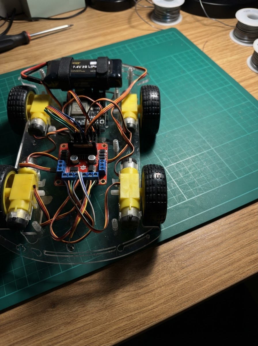
Build a wireless 4WD robot car controlled via Bluetooth from your smartphone or tablet. This project combines an ESP32 microcontroller with two L298N motor drivers to independently control four DC motors, allowing smooth forward, backward, and turning movements at adjustable speeds.
This guide provides a complete parts list, wiring diagram showing all motor and driver connections, step-by-step assembly instructions, and ready-to-upload firmware with Bluetooth command support. Follow along to create a fun platform for learning motor control, wireless communication, and robotics basics.
Wiring diagram

Gather all the parts
Assemble it in 9 steps
1. Gather everything
Lay out: ESP32 DevKit v1, 2× L298N motor driver modules, 4× DC gearbox motors (TT motors), 7.4V 2S LiPo battery pack, connecting wires, and the car chassis.
- TT motors come in wheel pairs — use 4 identical motors for consistent speed.
- A 2S LiPo (7.4V) is ideal: the L298N accepts 5–46V and its onboard 5V regulator powers the ESP32.
2. Mount motors and chassis
Attach all four DC motors to the chassis. Label them: Front-Left (FL), Rear-Left (RL), Front-Right (FR), Rear-Right (RR). Mount both L298N boards on the chassis.
- Keep left-side motors on one side, right-side on the other for clean wiring.
3. Wire motors to L298N drivers
LEFT L298N: Connect FL motor M+ to OUT1, M− to OUT2. Connect RL motor M+ to OUT3, M− to OUT4. RIGHT L298N: Connect FR motor M+ to OUT1, M− to OUT2. Connect RR motor M+ to OUT3, M− to OUT4.
- If a motor spins the wrong direction, swap its M+ and M− wires — no code change needed.
- Both motors on each channel are wired in parallel — total current per channel is doubled. Keep motor stall current per motor under 1A each (2A total per channel).
4. Connect battery to L298N drivers
Connect the LiPo battery BAT+ to the VS (motor power) screw terminal on the LEFT L298N. Also bridge VS to the RIGHT L298N's VS terminal. Connect BAT− to GND on BOTH L298N boards.
- Never reverse battery polarity — the L298N has no reverse-protection.
- Remove the 5V jumper on both L298N boards if it is present (the onboard regulator supplies 5V — the jumper connects external 5V instead of generating it).
5. Power the ESP32 from the L298N 5V output
Connect the 5V output pin of the LEFT L298N to the ESP32's VIN or 5V pin. Connect a GND from either L298N to the ESP32 GND pin.
- Make sure the L298N 5V jumper is removed before connecting the 5V pin, or you risk back-feeding the motor supply.
- Do NOT connect the LiPo directly to ESP32 — 7.4V will damage it.
6. Wire ESP32 to LEFT L298N control pins
LEFT L298N control wires from ESP32: • IN1 → GPIO27 • IN2 → GPIO26 • IN3 → GPIO25 • IN4 → GPIO33 • ENA → GPIO14 • ENB → GPIO13
- Use short, colour-coded jumper wires to avoid mistakes.
7. Wire ESP32 to RIGHT L298N control pins
RIGHT L298N control wires from ESP32: • IN1 → GPIO32 • IN2 → GPIO23 • IN3 → GPIO22 • IN4 → GPIO21 • ENA → GPIO19 • ENB → GPIO18
8. Double-check all connections
Verify: all four motors wired to their correct L298N outputs; both L298N GNDs share the same ground as the ESP32; no wires are loose on the screw terminals; 5V jumpers are removed from both L298N boards.
- Wiggle each screw terminal connector gently to confirm it is tight.
9. Power on and test via Bluetooth
Connect the LiPo battery. Use a Bluetooth serial terminal app (e.g. Serial Bluetooth Terminal on Android) to pair with '4WD_Car'. Send commands: • F = Forward • B = Backward • L = Turn Left • R = Turn Right • S = Stop • 1–9 = speed (9 = full speed)
- Start at speed '3' or '4' (send the digit) before driving — full speed on a small car is fast.
- If left or right motors spin wrong direction, swap their M+/M− wires at the L298N output terminals.
Review all connections
1. Connections between "battery" and "ESP32"
2. Connections between "l298n_left" and "ESP32"
3. Connections between "l298n_right" and "ESP32"
Deploy the firmware
#include <Arduino.h>
// ============================================================
//  4WD Bluetooth Car — ESP32 + 2x L298N
//  Layout:
//    L298N_LEFT  CHA (ENA) → Front-Left motor (OUT1/OUT2)
//                CHB (ENB) → Rear-Left  motor (OUT3/OUT4)
//    L298N_RIGHT CHA (ENA) → Front-Right motor (OUT1/OUT2)
//                CHB (ENB) → Rear-Right motor (OUT3/OUT4)
//
//  Bluetooth commands (send via serial BT terminal):
//    F = Forward    B = Backward
//    L = Turn Left  R = Turn Right
//    S = Stop
//    0-9 = speed (0=0% … 9=100%)
// ============================================================

#include "BluetoothSerial.h"

// ---- Pin definitions ----
#define LEFT_IN1  27
#define LEFT_IN2  26
#define LEFT_IN3  25
#define LEFT_IN4  33
#define LEFT_ENA  14
#define LEFT_ENB  13

#define RIGHT_IN1 32
#define RIGHT_IN2 23
#define RIGHT_IN3 22
#define RIGHT_IN4 21
#define RIGHT_ENA 19
#define RIGHT_ENB 18

// ---- LEDC PWM channels ----
#define CH_LEFT_A  0
#define CH_LEFT_B  1
#define CH_RIGHT_A 2
#define CH_RIGHT_B 3

#define PWM_FREQ   1000
#define PWM_RES    8        // 8-bit → 0-255


// Forward declarations
void setLeft(bool fwd, int spd);
void setRight(bool fwd, int spd);
void stopAll();

BluetoothSerial SerialBT;

int speed = 200;  // default speed (0-255)

// ---- Helpers ----
void setLeft(bool fwd, int spd) {
  digitalWrite(LEFT_IN1, fwd ? HIGH : LOW);
  digitalWrite(LEFT_IN2, fwd ? LOW  : HIGH);
  digitalWrite(LEFT_IN3, fwd ? HIGH : LOW);
  digitalWrite(LEFT_IN4, fwd ? LOW  : HIGH);
  ledcWrite(CH_LEFT_A, spd);
  ledcWrite(CH_LEFT_B, spd);
}

void setRight(bool fwd, int spd) {
  digitalWrite(RIGHT_IN1, fwd ? HIGH : LOW);
  digitalWrite(RIGHT_IN2, fwd ? LOW  : HIGH);
  digitalWrite(RIGHT_IN3, fwd ? HIGH : LOW);
  digitalWrite(RIGHT_IN4, fwd ? LOW  : HIGH);
  ledcWrite(CH_RIGHT_A, spd);
  ledcWrite(CH_RIGHT_B, spd);
}

void stopAll() {
  digitalWrite(LEFT_IN1,  LOW); digitalWrite(LEFT_IN2,  LOW);
  digitalWrite(LEFT_IN3,  LOW); digitalWrite(LEFT_IN4,  LOW);
  digitalWrite(RIGHT_IN1, LOW); digitalWrite(RIGHT_IN2, LOW);
  digitalWrite(RIGHT_IN3, LOW); digitalWrite(RIGHT_IN4, LOW);
  ledcWrite(CH_LEFT_A,  0); ledcWrite(CH_LEFT_B,  0);
  ledcWrite(CH_RIGHT_A, 0); ledcWrite(CH_RIGHT_B, 0);
}

void setup() {
  Serial.begin(115200);
  SerialBT.begin("4WD_Car");
  Serial.println("Bluetooth started — pair with '4WD_Car'");

  // Direction pins
  int dirPins[] = {LEFT_IN1, LEFT_IN2, LEFT_IN3, LEFT_IN4,
                   RIGHT_IN1, RIGHT_IN2, RIGHT_IN3, RIGHT_IN4};
  for (int p : dirPins) {
    pinMode(p, OUTPUT);
    digitalWrite(p, LOW);
  }

  // PWM (EN pins via LEDC)
  ledcSetup(CH_LEFT_A,  PWM_FREQ, PWM_RES);
  ledcSetup(CH_LEFT_B,  PWM_FREQ, PWM_RES);
  ledcSetup(CH_RIGHT_A, PWM_FREQ, PWM_RES);
  ledcSetup(CH_RIGHT_B, PWM_FREQ, PWM_RES);
  ledcAttachPin(LEFT_ENA,  CH_LEFT_A);
  ledcAttachPin(LEFT_ENB,  CH_LEFT_B);
  ledcAttachPin(RIGHT_ENA, CH_RIGHT_A);
  ledcAttachPin(RIGHT_ENB, CH_RIGHT_B);

  stopAll();
}

void loop() {
  if (SerialBT.available()) {
    char cmd = (char)SerialBT.read();

    // Speed adjustment: '0'-'9'
    if (cmd >= '0' && cmd <= '9') {
      speed = map(cmd - '0', 0, 9, 0, 255);
      SerialBT.printf("Speed set to %d%%\n", (speed * 100) / 255);
      return;
    }

    switch (cmd) {
      case 'F': case 'f':
        setLeft(true, speed);
        setRight(true, speed);
        SerialBT.println("Forward");
        break;

      case 'B': case 'b':
        setLeft(false, speed);
        setRight(false, speed);
        SerialBT.println("Backward");
        break;

      case 'L': case 'l':
        // Pivot left: right side forward, left side backward
        setLeft(false, speed);
        setRight(true,  speed);
        SerialBT.println("Turn Left");
        break;

      case 'R': case 'r':
        // Pivot right: left side forward, right side backward
        setLeft(true,  speed);
        setRight(false, speed);
        SerialBT.println("Turn Right");
        break;

      case 'S': case 's':
        stopAll();
        SerialBT.println("Stop");
        break;

      default:
        break;
    }
  }
}
Remix this project
Make it yours in one click
Open a full copy of this project in your own Schematik workspace — diagram, code, parts, and assembly steps included. Swap the sensor, add features, or redesign the whole thing with AI. The author's original stays untouched.