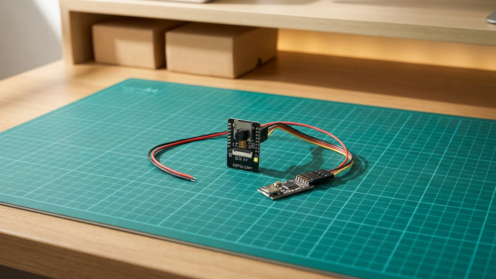
Schematik build
How to Build an ESP32 Video Doorbell
Local Wi-Fi live view with a real doorbell button, chime, and ring counter
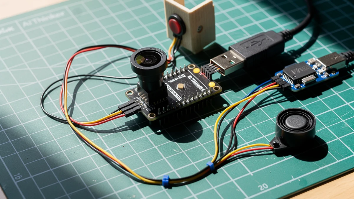
What you'll build
This guide turns an ESP32-CAM into a small local video doorbell. The board hosts a browser page on your 2.4 GHz Wi-Fi network, refreshes the camera feed every second, and shows a ring counter so you can tell when the physical button was pressed. A passive buzzer plays a short two-note chime when the button is pressed or the test-chime button is clicked in the browser, and the onboard flash LED blinks as a quick visual confirmation.
The hardware stays deliberately simple: an Ai-Thinker ESP32-CAM board, a SparkFun Beefy 3 FTDI programmer, one normally-open doorbell button on GPIO 13, and one passive piezo buzzer on GPIO 14. The sketch uses the internal pull-up for the button and the onboard GPIO 4 flash LED for feedback, so no resistors are needed beyond what the buzzer already has in its module.
Keep this as a private LAN prototype. It is a useful front-door, workshop, or room-alert build, but it is not an internet-exposed security product until you add authentication, HTTPS, weatherproofing, and a more permanent power plan. If you want the camera-only version first, start with the ESP32 Security Camera guide and then come back to add the doorbell interaction.
What you are building
The firmware has five jobs:
- initialise the OV2640 with the AI Thinker pin map,
- connect to your 2.4 GHz Wi-Fi network using
YOUR_WIFI_SSIDandYOUR_WIFI_PASSWORD, - serve a browser page with a ring counter, a "last pressed" timestamp, a live camera feed, and a test-chime button,
- respond to the physical button on
DOORBELL_BUTTON_PIN(GPIO 13) via interrupt, play the two-note chime onCHIME_PIN(GPIO 14), blink the flash LED onFLASH_LED_PIN(GPIO 4), and increment the ring count, - serve JPEG frames at
/captureand handle test-ring requests at/test-ring.
Cloud push, authentication, motion detection, and weatherproofing are outside this scope.
Upload and calibrate
Set the two Wi-Fi placeholders in the sketch before deploying:
const char* ssid     = "YOUR_WIFI_SSID";
const char* password = "YOUR_WIFI_PASSWORD";
After uploading and resetting, Serial Monitor at 115200 baud shows:
Video doorbell ready
Open http://192.168.x.x
Open that address from a browser on the same 2.4 GHz network. Press the physical button and confirm:
- the ring counter increments,
- the two-note chime plays (988 Hz then 1319 Hz),
- the flash LED blinks briefly.
Use the "Test chime" button in the browser to verify audio without physically pressing the button. If the feed is slow, change FRAMESIZE_VGA to FRAMESIZE_QVGA in the setupCamera() function. The page also auto-reloads every 10 seconds to keep the ring counter current.
Troubleshooting
- Camera init failed at boot. Wrong board profile selected, or the camera ribbon is not fully seated. Re-select the AI Thinker ESP32-CAM profile and reseat the ribbon.
- Button press is not detected or fires randomly. Check the GPIO 13 connection to GND. The interrupt fires on a falling edge, so a floating pin can cause spurious triggers. A short wire directly from the button to GND is more reliable than a long run.
- Chime sounds distorted or buzzer is silent. Confirm the passive buzzer signal is on GPIO 14. An active buzzer (with its own oscillator) will not play the
tone()melody and may produce a single fixed pitch; swap it for a passive one. - ESP32-CAM resets during capture or Wi-Fi connection. Supply current is too low. The camera and Wi-Fi together can exceed what some USB hubs provide; use a dedicated 5 V supply at 1 A or more.
- Browser ring counter does not update after a press. The page reloads every 10 seconds automatically, or click refresh manually. The
/test-ringroute also increments the counter if you want to test the full cycle. - Serial Monitor shows Wi-Fi connecting but never gets an IP. The network is probably 5 GHz-only. The ESP32-CAM supports 2.4 GHz only.
Going further
Once the doorbell is working locally, two natural extensions are push notifications and weatherproofing. For notifications, an MQTT publish on each ring event is straightforward; pair that with a Home Assistant automation or a Telegram bot and the ring reaches your phone without any cloud camera service.
For a more self-contained version that configures its own Wi-Fi credentials through a browser portal and can recover without reflashing, the ESP32-CAM Setup Portal Security Camera guide covers the Preferences-based credential storage pattern that slots cleanly into the doorbell code.
Wiring diagram
Gather all the parts
Assemble it in 5 steps
1. Prepare the ESP32-CAM
Seat the ESP32-CAM on its USB programmer adapter, connect it to your computer, and select the AI Thinker ESP32-CAM style board profile.
- Keep the camera ribbon fully seated before upload.
- Open the serial monitor at 115200 baud so you can read the local IP address.
- Unplug USB before reseating the ESP32-CAM. Offset headers can short 5V into the wrong pin.
2. Wire the doorbell button
Connect one side of the momentary button to GPIO13 and the other side to GND. The sketch uses the ESP32 internal pull-up, so no external resistor is needed for the basic build.
- Use short wires for the first test, then extend them once the enclosure layout is clear.
- Avoid GPIO0 for the doorbell button; it affects boot mode on many ESP32-CAM boards.
3. Add the local chime
Connect the passive buzzer signal pin to GPIO14 and its ground pin to GND. The onboard flash LED on GPIO4 is used as a short visual blink during each ring.
- If the chime is too quiet, use a small transistor driver or an active buzzer module instead of drawing extra current from the GPIO.
- Do not power a large speaker directly from an ESP32 GPIO pin.
4. Upload Wi-Fi details and test the feed
Replace the Wi-Fi placeholders, upload the sketch, then open the IP address printed in Serial Monitor from a browser on the same 2.4 GHz network. Press the button and confirm the ring count, chime, LED blink, and camera refresh all work.
- If the feed is slow, change FRAMESIZE_VGA to FRAMESIZE_QVGA.
- Keep this prototype on your private LAN unless you add authentication and HTTPS.
- Do not expose the camera page directly to the public internet.
5. Mount the prototype
Place the ESP32-CAM behind a faceplate or small enclosure so the lens has a clear view and the button is easy to press. Leave USB accessible while you are still tuning the sketch.
- A temporary cardboard faceplate is enough for testing camera angle before printing or drilling a permanent case.
- Weatherproofing and mains-powered doorbell transformer integration are outside this low-voltage prototype.
Review all connections
1. Connections between "doorbell-button-1" and "ESP32"
2. Connections between "doorbell-chime-1" and "ESP32"
3. Connections between "esp32-cam-doorbell-1" and "ESP32"
4. Connections between "esp32-video-doorbell-beefy3-programmer-1" and "ESP32"
5. Connections between "esp32-video-doorbell-regulated-5v-supply-1" and "ESP32"
6. Connections between "esp32-video-doorbell-usb-c-power-breakout-1" and "ESP32"
Deploy the firmware
#include "esp_camera.h"
#include <WiFi.h>
#include <WebServer.h>

const char* ssid = "YOUR_WIFI_SSID";
const char* password = "YOUR_WIFI_PASSWORD";

#define PWDN_GPIO_NUM     32
#define RESET_GPIO_NUM    -1
#define XCLK_GPIO_NUM      0
#define SIOD_GPIO_NUM     26
#define SIOC_GPIO_NUM     27
#define Y9_GPIO_NUM       35
#define Y8_GPIO_NUM       34
#define Y7_GPIO_NUM       39
#define Y6_GPIO_NUM       36
#define Y5_GPIO_NUM       21
#define Y4_GPIO_NUM       19
#define Y3_GPIO_NUM       18
#define Y2_GPIO_NUM        5
#define VSYNC_GPIO_NUM    25
#define HREF_GPIO_NUM     23
#define PCLK_GPIO_NUM     22

#define DOORBELL_BUTTON_PIN 13
#define CHIME_PIN 14
#define FLASH_LED_PIN 4

WebServer server(80);
volatile bool buttonPressed = false;
unsigned long lastRingMs = 0;
unsigned long ringCount = 0;

void IRAM_ATTR onDoorbellPress() {
  buttonPressed = true;
}

String htmlPage() {
  String ringState = ringCount == 0 ? "Waiting for the first press" : "Last press " + String((millis() - lastRingMs) / 1000) + " seconds ago";
  String page = "<!doctype html><html><head><meta name='viewport' content='width=device-width, initial-scale=1'>";
  page += "<title>ESP32 Video Doorbell</title><style>body{font-family:sans-serif;background:#111;color:#fff;margin:0;padding:24px;text-align:center}";
  page += "img{width:100%;max-width:640px;border-radius:18px;border:1px solid #333}.card{max-width:680px;margin:auto}.badge{display:inline-block;background:#0f766e;padding:8px 12px;border-radius:999px;margin:12px}</style></head>";
  page += "<body><div class='card'><h1>ESP32 Video Doorbell</h1><div class='badge'>Rings: " + String(ringCount) + "</div><p>" + ringState + "</p>";
  page += "<img src='/capture' id='cam'><p><button onclick=\"fetch('/test-ring')\">Test chime</button></p>";
  page += "<script>setInterval(()=>{document.getElementById('cam').src='/capture?t='+Date.now()},800);setInterval(()=>location.reload(),10000)</script>";
  page += "</div></body></html>";
  return page;
}

void playChime() {
  digitalWrite(FLASH_LED_PIN, HIGH);
  tone(CHIME_PIN, 988, 120);
  delay(160);
  tone(CHIME_PIN, 1319, 180);
  delay(220);
  noTone(CHIME_PIN);
  digitalWrite(FLASH_LED_PIN, LOW);
}

void handleRoot() {
  server.send(200, "text/html", htmlPage());
}

void handleCapture() {
  camera_fb_t *fb = esp_camera_fb_get();
  if (!fb) {
    server.send(500, "text/plain", "Camera capture failed");
    return;
  }
  server.sendHeader("Cache-Control", "no-store");
  server.send_P(200, "image/jpeg", (const char *)fb->buf, fb->len);
  esp_camera_fb_return(fb);
}

void handleTestRing() {
  lastRingMs = millis();
  ringCount++;
  playChime();
  server.send(200, "text/plain", "Doorbell test ring recorded");
}

void setupCamera() {
  camera_config_t config;
  config.ledc_channel = LEDC_CHANNEL_0;
  config.ledc_timer = LEDC_TIMER_0;
  config.pin_d0 = Y2_GPIO_NUM;
  config.pin_d1 = Y3_GPIO_NUM;
  config.pin_d2 = Y4_GPIO_NUM;
  config.pin_d3 = Y5_GPIO_NUM;
  config.pin_d4 = Y6_GPIO_NUM;
  config.pin_d5 = Y7_GPIO_NUM;
  config.pin_d6 = Y8_GPIO_NUM;
  config.pin_d7 = Y9_GPIO_NUM;
  config.pin_xclk = XCLK_GPIO_NUM;
  config.pin_pclk = PCLK_GPIO_NUM;
  config.pin_vsync = VSYNC_GPIO_NUM;
  config.pin_href = HREF_GPIO_NUM;
  config.pin_sccb_sda = SIOD_GPIO_NUM;
  config.pin_sccb_scl = SIOC_GPIO_NUM;
  config.pin_pwdn = PWDN_GPIO_NUM;
  config.pin_reset = RESET_GPIO_NUM;
  config.xclk_freq_hz = 20000000;
  config.pixel_format = PIXFORMAT_JPEG;
  config.frame_size = FRAMESIZE_VGA;
  config.jpeg_quality = 12;
  config.fb_count = 1;

  if (esp_camera_init(&config) != ESP_OK) {
    Serial.println("Camera init failed. Check board type and ribbon cable.");
    while (true) delay(1000);
  }
}

void setup() {
  Serial.begin(115200);
  Serial.setDebugOutput(false);
  delay(300);

  pinMode(DOORBELL_BUTTON_PIN, INPUT_PULLUP);
  pinMode(CHIME_PIN, OUTPUT);
  pinMode(FLASH_LED_PIN, OUTPUT);
  digitalWrite(FLASH_LED_PIN, LOW);
  attachInterrupt(digitalPinToInterrupt(DOORBELL_BUTTON_PIN), onDoorbellPress, FALLING);

  setupCamera();

  WiFi.begin(ssid, password);
  Serial.print("Connecting to Wi-Fi");
  while (WiFi.status() != WL_CONNECTED) {
    delay(500);
    Serial.print(".");
  }

  server.on("/", handleRoot);
  server.on("/capture", handleCapture);
  server.on("/test-ring", handleTestRing);
  server.begin();

  Serial.println();
  Serial.println("Video doorbell ready");
  Serial.print("Open http://");
  Serial.println(WiFi.localIP());
}

void loop() {
  server.handleClient();

  if (buttonPressed && millis() - lastRingMs > 500) {
    buttonPressed = false;
    lastRingMs = millis();
    ringCount++;
    Serial.print("Doorbell pressed. Ring count: ");
    Serial.println(ringCount);
    playChime();
  }
}
Remix this project
Make it yours in one click
Open a full copy of this project in your own Schematik workspace — diagram, code, parts, and assembly steps included. Swap the sensor, add features, or redesign the whole thing with AI. The author's original stays untouched.
Related projects
How to Build an ESP32 Security Camera
ESP32 · Beginner · 25 minutes · July 22, 2026Schematik
How to Build an RFID Treasure Chest with ESP32
ESP32 · Intermediate · 50 minutes · June 12, 2026Schematik
How to Build an ESP32 Weather Station with Clothing Advice
ESP32 · Intermediate · 30 minutes · June 12, 2026Schematik