Schematik build
How to Build an ESP32 Security Camera
Stream a tiny ESP32-CAM over your local Wi-Fi network
What you'll build
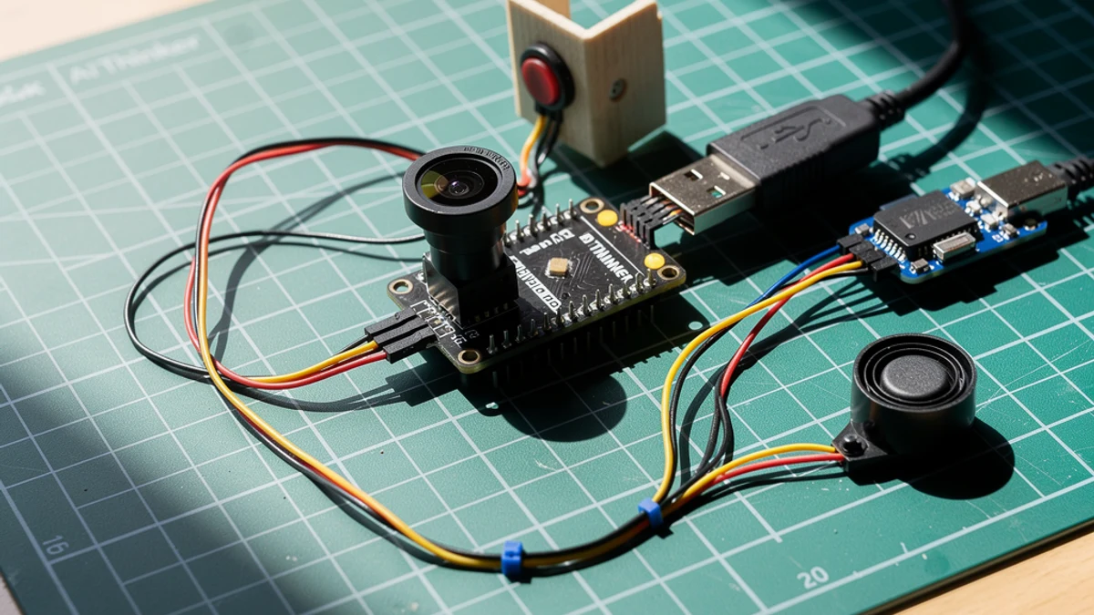
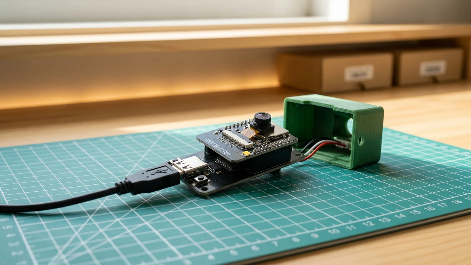
This guide turns the Ai-Thinker ESP32-CAM board into a local Wi-Fi security camera. Its OV2640 camera signal pins are fixed PCB traces, so there is no camera breakout to wire. The external flashing hardware is the SparkFun Beefy 3 FTDI programmer and a Micro USB data cable.
Once the sketch is deployed, the board joins your 2.4 GHz Wi-Fi network and prints a local address in Serial Monitor. Open that address from any browser on the same network and you get a simple page that refreshes live captures from the camera every 700 milliseconds.
The stream stays local and the code stays simple. It is a practical starting point before adding authentication, motion detection, a battery, or a more permanent mount. This project came from Sam's Schematik Short, which you can watch on YouTube.
What you are building
This guide covers a local-network camera only. The firmware has four jobs:
- initialise the OV2640 with the AI Thinker pin map,
- connect to your 2.4 GHz Wi-Fi network using
YOUR_WIFI_SSIDandYOUR_WIFI_PASSWORD, - serve a root page that auto-refreshes captures at
/captureevery 700 ms, - return JPEG frames from the camera buffer on each request to
/capture.
Push notification, authentication, cloud storage, and motion detection are out of scope.
Upload and calibrate
Open the sketch in Schematik and set the two Wi-Fi placeholders before deploying:
const char* ssid     = "YOUR_WIFI_SSID";
const char* password = "YOUR_WIFI_PASSWORD";
Deploy from the Schematik project page, then open Serial Monitor at 115200 baud. After the board connects you will see:
Security camera ready
Open http://192.168.x.x
Open that address in a browser on the same 2.4 GHz network. The page loads a JPEG image that refreshes automatically. If the frame rate feels slow, change FRAMESIZE_VGA to FRAMESIZE_QVGA in the camera config for a faster but smaller image.
Do not commit or share the sketch with real Wi-Fi credentials in it.
Troubleshooting
- "Camera init failed" in Serial Monitor. The board type is probably wrong. Select the AI Thinker ESP32-CAM profile, not a generic ESP32 DevKit. Also check that the camera ribbon is fully clipped into the socket.
- No serial port appears after connecting USB. The cable is likely charge-only. Swap it for a cable that transfers data — the port should appear in the OS device list immediately.
- Board does not enter upload mode. Make sure IO0 is connected to GND before pressing upload, then remove the link before resetting.
- ESP32-CAM resets or drops connection during capture. Confirm the camera uses the regulated 5 V rail, Beefy 3 VCC is disconnected, and all grounds are shared.
- Browser page loads but image is black or corrupted. Power-cycle the board. The OV2640 occasionally needs a clean reset to initialise correctly after a flash.
- "Connection refused" when opening the IP address. The board has not finished connecting to Wi-Fi. Wait a few seconds and refresh; Serial Monitor will show the IP once the server starts.
Going further
Once the basic stream is reliable, the natural next step is to add a motion-detection pass in the capture loop: compare consecutive JPEG buffers and trigger an alert when enough pixels change. Pair that with an MQTT publish or a simple HTTP webhook call and you have a basic event-driven camera without any external cloud dependency.
For a version that sets itself up without editing credentials and supports recovery without reflashing, see the ESP32-CAM Setup Portal Security Camera guide, which adds a browser-based Wi-Fi configuration page and a power-cycle reset path.
Wiring diagram
Gather all the parts
Assemble it in 4 steps
1. Seat the ESP32-CAM on the USB adapter
Align the ESP32-CAM headers with the programmer adapter and press the board down evenly. Keep the camera ribbon seated and avoid touching the lens.
- The Short uses a tiny USB adapter, so you do not need loose jumper wires for this version.
- If your adapter has boot/upload buttons, leave them accessible while flashing.
- Unplug USB before reseating the ESP32-CAM on the adapter. Offset headers can short 5V into the wrong pin.
2. Connect USB and choose the ESP32-CAM board
Connect the adapter to your computer with a USB data cable. In Schematik or the Arduino tooling, use the AI Thinker ESP32-CAM style pinout unless your module says otherwise.
- Open the serial monitor at 115200 baud so you can read the local IP address after upload.
- If no port appears, try another USB cable before changing code.
- The camera signal pins are built into the ESP32-CAM module. Do not add jumper wires for the camera itself.
- Some charge-only USB cables power the board but cannot upload sketches.
3. Add Wi-Fi details and deploy
Replace YOUR_WIFI_SSID and YOUR_WIFI_PASSWORD in the sketch, then deploy it to the ESP32-CAM. The code starts a small web server on your local network.
- Use a 2.4 GHz Wi-Fi network. Most ESP32-CAM modules cannot join 5 GHz-only networks.
- Keep the board close to the router for the first test.
- Do not commit or share a version of the sketch with real Wi-Fi credentials in it.
4. Open the local camera page
After the board restarts, read the IP address printed in serial output and open it in a browser on the same Wi-Fi network. The page refreshes camera captures to give you a simple live view.
- If the page loads slowly, lower the frame size from FRAMESIZE_VGA to FRAMESIZE_QVGA.
- Use this as a local prototype, not an internet-exposed security system.
- Keep the camera stream on your private LAN unless you add authentication and HTTPS.
Review all connections
1. Connections between "esp32-cam-camera-1" and "ESP32"
2. Connections between "esp32-security-camera-beefy3-programmer-1" and "ESP32"
3. Connections between "esp32-security-camera-regulated-5v-supply-1" and "ESP32"
4. Connections between "esp32-security-camera-usb-c-power-breakout-1" and "ESP32"
Deploy the firmware
#include "esp_camera.h"
#include <WiFi.h>
#include <WebServer.h>

const char* ssid = "YOUR_WIFI_SSID";
const char* password = "YOUR_WIFI_PASSWORD";

#define PWDN_GPIO_NUM     32
#define RESET_GPIO_NUM    -1
#define XCLK_GPIO_NUM      0
#define SIOD_GPIO_NUM     26
#define SIOC_GPIO_NUM     27
#define Y9_GPIO_NUM       35
#define Y8_GPIO_NUM       34
#define Y7_GPIO_NUM       39
#define Y6_GPIO_NUM       36
#define Y5_GPIO_NUM       21
#define Y4_GPIO_NUM       19
#define Y3_GPIO_NUM       18
#define Y2_GPIO_NUM        5
#define VSYNC_GPIO_NUM    25
#define HREF_GPIO_NUM     23
#define PCLK_GPIO_NUM     22

WebServer server(80);

void handleRoot() {
  server.send(200, "text/html",
    "<!doctype html><html><head><meta name='viewport' content='width=device-width, initial-scale=1'>"
    "<title>ESP32 Security Camera</title>"
    "<style>body{font-family:sans-serif;background:#111;color:#fff;text-align:center;margin:0;padding:2rem}"
    "img{width:100%;max-width:640px;border-radius:16px}</style></head>"
    "<body><h1>ESP32 Security Camera</h1><img src='/capture' id='cam'>"
    "<script>setInterval(()=>{document.getElementById('cam').src='/capture?t='+Date.now()},700)</script>"
    "</body></html>"
  );
}

void handleCapture() {
  camera_fb_t *fb = esp_camera_fb_get();
  if (!fb) {
    server.send(500, "text/plain", "Camera capture failed");
    return;
  }

  server.sendHeader("Cache-Control", "no-store");
  server.send_P(200, "image/jpeg", (const char *)fb->buf, fb->len);
  esp_camera_fb_return(fb);
}

void setup() {
  Serial.begin(115200);
  Serial.setDebugOutput(false);
  delay(300);

  camera_config_t config;
  config.ledc_channel = LEDC_CHANNEL_0;
  config.ledc_timer = LEDC_TIMER_0;
  config.pin_d0 = Y2_GPIO_NUM;
  config.pin_d1 = Y3_GPIO_NUM;
  config.pin_d2 = Y4_GPIO_NUM;
  config.pin_d3 = Y5_GPIO_NUM;
  config.pin_d4 = Y6_GPIO_NUM;
  config.pin_d5 = Y7_GPIO_NUM;
  config.pin_d6 = Y8_GPIO_NUM;
  config.pin_d7 = Y9_GPIO_NUM;
  config.pin_xclk = XCLK_GPIO_NUM;
  config.pin_pclk = PCLK_GPIO_NUM;
  config.pin_vsync = VSYNC_GPIO_NUM;
  config.pin_href = HREF_GPIO_NUM;
  config.pin_sccb_sda = SIOD_GPIO_NUM;
  config.pin_sccb_scl = SIOC_GPIO_NUM;
  config.pin_pwdn = PWDN_GPIO_NUM;
  config.pin_reset = RESET_GPIO_NUM;
  config.xclk_freq_hz = 20000000;
  config.pixel_format = PIXFORMAT_JPEG;
  config.frame_size = FRAMESIZE_VGA;
  config.jpeg_quality = 12;
  config.fb_count = 1;

  if (esp_camera_init(&config) != ESP_OK) {
    Serial.println("Camera init failed. Check the board type and camera ribbon.");
    return;
  }

  WiFi.begin(ssid, password);
  Serial.print("Connecting to Wi-Fi");
  while (WiFi.status() != WL_CONNECTED) {
    delay(500);
    Serial.print(".");
  }

  server.on("/", handleRoot);
  server.on("/capture", handleCapture);
  server.begin();

  Serial.println();
  Serial.println("Security camera ready");
  Serial.print("Open http://");
  Serial.println(WiFi.localIP());
}

void loop() {
  server.handleClient();
}
Remix this project
Make it yours in one click
Open a full copy of this project in your own Schematik workspace — diagram, code, parts, and assembly steps included. Swap the sensor, add features, or redesign the whole thing with AI. The author's original stays untouched.
Related projects
How to Build an RFID Treasure Chest with ESP32
ESP32 · Intermediate · 50 minutes · June 12, 2026Schematik
How to Build an ESP32 Weather Station with Clothing Advice
ESP32 · Intermediate · 30 minutes · June 12, 2026Schematik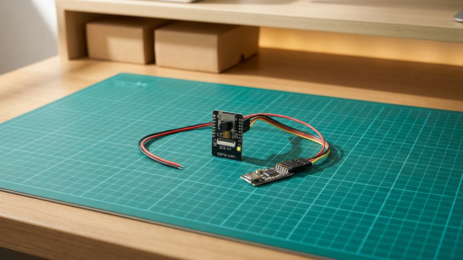
How to Build an ESP32-CAM Setup Portal Security Camera
ESP32 · Intermediate · 35 minutes · July 22, 2026Schematik