Community project
CyberPet Cube Companion
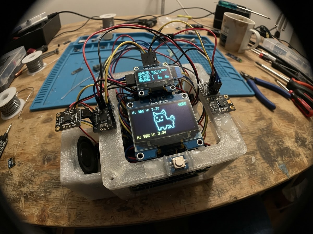
CyberPet Cube Companion is an interactive AI-powered desktop pet built around an ESP32-S3 microcontroller. The project combines a 1.5" OLED face display, camera vision, spatial awareness via IMU and gesture sensors, audio input/output, and servo-driven articulation to create a responsive creature that reacts to its environment, learns user habits, and connects to cloud AI services.
This guide provides a complete wiring diagram, detailed parts list, and step-by-step assembly instructions for integrating the camera module, dual I2S audio chain, sensor cluster, and servo mechanics. You'll also get the modular firmware architecture that orchestrates face animations, acoustic events, kinematics control, and machine learning personality persistence across power cycles.
Wiring diagram

Gather all the parts
Assemble it in 12 steps
1. Gather all components
Lay out all components before soldering. Check the LiPo for puffing or damage. Confirm the IP5306 module has a USB-C port and a push-button for power on/off.
- Keep the LiPo away from sharp tools.
- Photograph your component bag now for reference.
2. Wire the power chain
Connect the LiPo BAT+ and BAT- to the IP5306 module's BAT+ and BAT- pads. Connect the IP5306 VOUT+ to the ESP32-S3 DevKitM-1 N16R8's 5V pin and VOUT- to GND. Solder the 1000µF 16V electrolytic capacitor directly across the 5V and GND rails near the servo connector — positive leg to 5V, negative leg to GND. Double-check polarity on the capacitor and battery.
- Reversed LiPo polarity will destroy the IP5306 instantly.
- Reversed capacitor polarity causes it to heat up and explode — the stripe on the body marks the NEGATIVE leg.
3. Mount and wire the OLED display (one at a time)
For production build: install the Waveshare 1.5" SSD1327 OLED (oled_main). For prototype testing: install the 0.96" SPI OLED (oled_proto) on the 3D-printed adapter plate instead. Both displays share the same 4 wires: MOSI→GPIO11, CLK→GPIO12, DC→GPIO43, RST→GPIO44. The ONLY difference is the CS pin: main OLED CS→GPIO10, proto OLED CS→GPIO13. Wire VCC→3.3V, GND→GND. Only install ONE display at a time.
- Do not install both OLEDs simultaneously — they share DC and RST lines.
- To switch displays: comment/uncomment the #define DISPLAY_MAIN / #define DISPLAY_PROTO line at the top of firmware.cpp and hit Deploy.
4. Install the camera (OV3660) — PWDN and RESET tie-offs
IMPORTANT: This build frees GPIO19 and GPIO20 (previously cam PWDN/RESET) for the microphone. To do this, tie two camera pins in hardware: solder a wire from OV3660 PWDN directly to GND (always-on), and solder a wire from OV3660 RESET directly to 3.3V (held out of reset). Connect the OV3660 24-pin FPC ribbon to the carrier PCB. Route ribbon through the hollow neck core. Camera 3V3 connects to the privacy switch SW_OUT. DVP pins: D0→15, D1→7, D2→6, D3→5, D4→4, D5→2, D6→48, D7→47, VSYNC→46, HREF→45, PCLK→21, XCLK→14. SIOD→GPIO8, SIOC→GPIO9.
- Tying PWDN to GND and RESET to 3V3 is safe for always-on use — the camera simply stays powered and un-reset at all times.
- FPC ribbon is fragile. Insert connector-first and latch the ZIF tab before any power-on.
- Do not flex the ribbon sharply or it will fracture internally.
5. Wire the I2S microphone (INMP441)
The N16R8 module reserves GPIO35, 36, and 37 for its internal 8MB Octal PSRAM bus — those pins are NOT usable externally. The INMP441 has been moved to the freed camera pins: SCK→GPIO19, WS→GPIO20, SD→GPIO39. VDD routes through privacy switch SW_OUT (physical toggle cuts mic power). GND→GND, L/R→GND (left channel mono). Route the mic cable up through the neck into the head shell.
- L/R tied to GND = left channel. This is correct for mono capture.
- DO NOT wire anything to GPIO33, 34, 35, 36, or 37 on the N16R8 — these are internally connected to the PSRAM chip inside the module.
- GPIO35/36/37 look like normal pins on the header but driving them will corrupt PSRAM and crash the ESP32-S3.
6. Wire the MAX98357A amplifier and speaker
Connect MAX98357A: VIN→5V, GND→GND, BCLK→GPIO41, LRC→GPIO42, DIN→GPIO40. Connect the 40mm speaker to SPK+ and SPK- terminals. The MAX98357A runs on 5V but its BCLK/LRC/DIN logic inputs are 3.3V compatible — no level shifting needed.
- Hot-glue the speaker to the inside of the base shell facing outward.
- Leave the GAIN pin floating for 9dB gain (default) or wire to GND for 12dB.
7. Wire the I2C sensor cluster
Both APDS9960 and MPU6050 share the I2C bus: SDA→GPIO8, SCL→GPIO9. Wire MPU6050 INT→GPIO38. The APDS9960 INT pin is NOT wired in this build — the sensor is polled via I2C inside a FreeRTOS task instead, freeing GPIO39 for the microphone SD line. Mount APDS9960 in the front of the head module pointing outward. Mount MPU6050 flat inside the base. Both run on 3.3V.
- Twist the SDA/SCL wires together for noise immunity.
- APDS9960 default I2C address is 0x39; MPU6050 default is 0x68 — no address conflict.
- Polling APDS via I2C in a FreeRTOS task every 50ms is plenty fast for gesture detection.
8. Install the TTP223 touch sensor
Glue the TTP223 module flat against the inside of the top shell with the sensing pad facing the acrylic glass. Connect: VCC→3.3V, GND→GND, SIG→GPIO1.
- Use thin double-sided tape, not hot-glue, to avoid changing the capacitive sensitivity.
9. Mount the servos and route wiring harness
Mount servo_pan (left/right) on the base bracket and servo_tilt (up/down) on the neck pivot bracket. Thread wiring through the hollow neck core. Connect: Pan SIGNAL→GPIO16, Tilt SIGNAL→GPIO17, both VCC→5V, both GND→GND. Center both servos to 90° before mechanically fastening the horn.
- 3.3V GPIO to 5V servo signal: SG90 servos generally accept 3.3V PWM but this is at the low end of spec. If servo control is erratic, add a BSS138 or TXB0104 level shifter on GPIO16 and GPIO17.
10. Wire the piezo vibration sensor
Solder the piezo ceramic disk to a small PCB footprint at the base. Connect the positive terminal to GPIO3 (ADC1_CH2) and negative to GND. Add a 1MΩ resistor across OUT and GND as a bleed resistor to prevent charge buildup and floating reads.
- The 1MΩ bleed resistor limits charge buildup and prevents ADC latch-up from piezo spikes.
11. Install the privacy switch and red LED
Mount the physical toggle switch on the rear face of the cube. SW_IN connects to 3.3V rail; SW_OUT feeds both the INMP441 VDD and OV3660 3V3 — when the switch is OFF, both mic and camera lose power simultaneously. Red LED chain: GPIO18 → 220Ω resistor → LED anode → LED cathode → GND. Mount the LED next to the switch so it illuminates when privacy mode is active.
- Test with a multimeter that SW_OUT truly drops to 0V when toggled before closing the enclosure.
12. Final assembly and first boot
Tuck all wiring into the enclosure. Press-fit the acrylic face plate. Connect USB-C to the IP5306 charge port to charge the LiPo first (green LED on IP5306). Press the IP5306 power button once to turn on. The OLED should display 'CyberPet V4 Booting...' within 2 seconds.
- If nothing appears on the OLED, check that DISPLAY_MAIN (or DISPLAY_PROTO) is defined and the correct CS pin is wired.
- Use Schematik's Deploy button to flash firmware — no external IDE needed.
- Never charge the LiPo unattended for the first cycle.
- Verify the 1000µF capacitor polarity before powering the servos.
Review all connections
1. Connections between "battery" and "ESP32"
2. Connections between "ip5306" and "ESP32"
3. Connections between "privacy_switch" and "ESP32"
4. Connections between "res_privacy_led" and "ESP32"
5. Connections between "oled_main" and "ESP32"
6. Connections between "oled_proto" and "ESP32"
7. Connections between "inmp441" and "ESP32"
8. Connections between "max98357a" and "ESP32"
9. Connections between "apds9960" and "ESP32"
10. Connections between "mpu6050" and "ESP32"
11. Connections between "ttp223" and "ESP32"
12. Connections between "servo_pan" and "ESP32"
13. Connections between "servo_tilt" and "ESP32"
14. Connections between "cap_1000uf" and "ESP32"
15. Connections between "piezo_sensor" and "ESP32"
16. Connections between "ov3660" and "ESP32"
Deploy the firmware
// ============================================================
//  CyberPet V4 — main.cpp
//  Orchestrator only. No business logic lives here.
//
//  Board : ESP32-S3-DevKitM-1 N16R8 (16 MB flash, 8 MB Octal PSRAM)
//  Power : 2x WLY102050 1000mAh LiPo in PARALLEL -> 3.7V / 2000mAh
//          -> CD42 IP5306 boost -> 5V rail -> ESP32-S3 5V pin
//          PARALLEL = 3.7V always. NEVER assume 7.4V series.
//
//  GPIO 33-37: RESERVED for Octal PSRAM. Do not wire or write.
//
//  Feature modules:
//    Config.h              -- pins, constants, enums, shared state
//    Sensors.h/.cpp        -- APDS9960, MPU6050, TTP223, Piezo, IP5306
//    Display_Face.h/.cpp   -- LovyanGFX sprite engine, 20 animations
//    Audio_AI.h/.cpp       -- INMP441 RX, MAX98357A TX, acoustic events
//    Kinematics.h/.cpp     -- eased servo control, jaw sync, shiver
//    MachineLearning.h/.cpp -- NVS, Echo Drift, personality, habits
//    WiFi_Cloud.h/.cpp     -- Wi-Fi, NTP, OWM weather, cloud AI bridge
// ============================================================

#include <Arduino.h>
#include <Wire.h>
#include "freertos/FreeRTOS.h"
#include "freertos/task.h"
#include "freertos/semphr.h"

#include "Config.h"
#include "Sensors.h"
#include "Display_Face.h"
#include "Audio_AI.h"
#include "Kinematics.h"
#include "MachineLearning.h"
#include "WiFi_Cloud.h"

#define I2C_SDA 8
#define I2C_SCL 9
#define PRIVACY_LED 18

// Pin constants (I2C_SDA, I2C_SCL, PRIVACY_LED) come from Config.h.
// The #defines below are redundant with Config.h — remove to avoid redefinition.
// (kept as comments for cross-reference during hardware assembly)
// I2C_SDA = 8, I2C_SCL = 9, PRIVACY_LED = 18

// ─────────────────────────────────────────────────────────────
//  SHARED GLOBAL STATE DEFINITIONS
//  (declared extern in Config.h; defined once here)
// ─────────────────────────────────────────────────────────────

// Forward declarations
static Mood vibeToMood(float v);
static void taskPrivacyMonitor(void* pv);
static void taskMoodReactor(void* pv);
static void taskWeatherReactor(void* pv);
static void taskBatteryDrama(void* pv);

volatile float            g_vibeScore       = 50.0f;
volatile Mood             g_currentMood     = MOOD_CONTENT;
volatile bool             g_privacyMode     = false;
volatile bool             g_audioPlaying    = false;
volatile uint8_t          g_batteryPct      = 100;
volatile WeatherCondition g_weather         = WX_CLEAR;
volatile float            g_tempC           = 20.0f;
volatile PowerMode        g_powerMode       = POWER_UPS;   // UPS assumed at boot
volatile bool             g_dramaModeActive = false;        // set by Sensors_Task
SemaphoreHandle_t         g_moodMutex       = nullptr;
SemaphoreHandle_t         g_servoMutex      = nullptr;

// ─────────────────────────────────────────────────────────────
//  MOOD MAPPING  (vibe score -> Mood enum)
// ─────────────────────────────────────────────────────────────
static Mood vibeToMood(float v) {
  if (v >= 90.0f) return MOOD_ECSTATIC;
  if (v >= 75.0f) return MOOD_HAPPY;
  if (v >= 65.0f) return MOOD_AFFECTIONATE;
  if (v >= 55.0f) return MOOD_CONTENT;
  if (v >= 45.0f) return MOOD_EAGER;
  if (v >= 35.0f) return MOOD_WONDER;
  if (v >= 25.0f) return MOOD_SAD;
  if (v >= 15.0f) return MOOD_LONELY;
  if (v >= 10.0f) return MOOD_ANXIOUS;
  if (v >=  5.0f) return MOOD_PANIC;
  return MOOD_REGRETFUL;
}

// ─────────────────────────────────────────────────────────────
//  PRIVACY PIN MONITOR TASK
//  Physical switch cuts 3.3V to mic + camera; GPIO18 goes LOW.
//  This task detects that and sets g_privacyMode accordingly.
// ─────────────────────────────────────────────────────────────
static void taskPrivacyMonitor(void* pv) {
  bool lastState = false;
  while (true) {
    bool currentState = (digitalRead(PRIVACY_LED) == LOW);
    if (currentState != lastState) {
      lastState     = currentState;
      g_privacyMode = currentState;
      WiFi_SetPrivacyMode(currentState);
      if (currentState) {
        Serial.println("[PRIV] Privacy mode ON -- mic + camera power cut");
        Display_ShowPrivacyMode();
      } else {
        Serial.println("[PRIV] Privacy mode OFF");
        Display_SetMood(g_currentMood);
      }
    }
    vTaskDelay(pdMS_TO_TICKS(200));
  }
}

// ─────────────────────────────────────────────────────────────
//  MOOD REACTOR TASK
//  Reads sensor events every 100 ms and applies mood hierarchy.
//  Priority order (highest first):
//    1. MPU6050 drop/shake/upside-down  (dizzy overrides all)
//    2. Piezo impact                    (angry/scared)
//    3. Audio events                    (loud/whisper/rhythm)
//    4. Touch events                    (happy, spam -> annoyance)
//    5. APDS9960 gesture / proximity
//    6. Baseline vibe drift from ML
//
//  DRAMA MODE GATE: when g_dramaModeActive is true, high-energy
//  Kinematics calls (sweeps, wobbles, snaps) are skipped. The
//  robot still reacts emotionally (face animations, tones) but
//  conserves power by not running servos unnecessarily.
// ─────────────────────────────────────────────────────────────
static void taskMoodReactor(void* pv) {
  SensorEvents ev;
  Mood         lastMood = MOOD_CONTENT;

  while (true) {
    Sensors_GetEvents(ev);
    Sensors_ClearEvents();

    // Drama gate: block high-energy servo moves in POWER_DRAMA
    bool servoOk = !g_dramaModeActive;

    // ── Priority 1: Motion extremes ───────────────────────────
    if (ev.dropped) {
      if (servoOk) Kinematics_Wobble(6, 20);
      Display_SetAnim(ANIM_SPIRAL_DIZZY);
      vTaskDelay(pdMS_TO_TICKS(800));
    } else if (ev.shake) {
      if (servoOk) Kinematics_Wobble(8, 25);
      Display_SetAnim(ANIM_SPIRAL_DIZZY);
      vTaskDelay(pdMS_TO_TICKS(600));
    } else if (ev.upsideDown) {
      Display_SetAnim(ANIM_PANIC);
      if (servoOk) Kinematics_MoveTo(SERVO_CENTER, SERVO_TILT_MAX, 6, 10);
    }

    // ── Priority 2: Desk impact ───────────────────────────────
    else if (ev.piezoHit) {
      if (ev.rhythmicClap) {
        Display_SetAnim(ANIM_EAGER);
        if (servoOk) {
          Kinematics_MoveTo(SERVO_CENTER - 20, SERVO_CENTER, 4, 8);
          vTaskDelay(pdMS_TO_TICKS(200));
          Kinematics_MoveTo(SERVO_CENTER + 20, SERVO_CENTER, 4, 8);
          vTaskDelay(pdMS_TO_TICKS(200));
          Kinematics_Center();
        }
      } else {
        Display_SetAnim(ANIM_SQUINT_ANGRY);
        if (servoOk) {
          Kinematics_HeadSnap(SERVO_CENTER, SERVO_TILT_MIN + 10);
          vTaskDelay(pdMS_TO_TICKS(400));
          Kinematics_Center();
        }
      }
      ML_LogAudioInteraction(AUD_EVT_LOUD);
    }

    // ── Priority 3: Audio events ──────────────────────────────
    else {
      AudioEvent aev = Audio_PollEvent();
      switch (aev) {
        case AUD_EVT_LOUD:
          Display_SetAnim(ANIM_PANIC);
          if (servoOk) Kinematics_HeadSnap(SERVO_CENTER, SERVO_TILT_MIN + 15);
          ML_LogAudioInteraction(AUD_EVT_LOUD);
          break;
        case AUD_EVT_SUSTAINED:
          Display_SetAnim(ANIM_SQUINT_ANGRY);
          break;
        case AUD_EVT_SILENCE:
          Display_SetAnim(ANIM_WONDER);
          if (servoOk) {
            Kinematics_MoveTo(SERVO_CENTER - 15, SERVO_CENTER, 8, 12);
            vTaskDelay(pdMS_TO_TICKS(300));
            Kinematics_Center();
          }
          break;
        case AUD_EVT_WHISPER:
          Display_SetAnim(ANIM_AFFECTIONATE);
          if (servoOk) Kinematics_MoveTo(SERVO_CENTER, SERVO_CENTER + 10, 10, 14);
          ML_LogAudioInteraction(AUD_EVT_WHISPER);
          break;
        case AUD_EVT_RHYTHM:
          Display_SetAnim(ANIM_ECSTATIC);
          if (servoOk) Kinematics_Wobble(4, 12);
          ML_LogAudioInteraction(AUD_EVT_RHYTHM);
          break;
        case AUD_EVT_WAKEWORD:
          Display_SetAnim(ANIM_EAGER);
          if (servoOk) Kinematics_Center();
          break;
        default: break;
      }

      // ── Priority 4: Touch ─────────────────────────────────
      if (ev.touched) {
        if (ev.touchSpam) {
          Display_SetAnim(ANIM_SQUINT_ANGRY);
        } else {
          Display_SetAnim(ANIM_AFFECTIONATE);
          if (servoOk) {
            Kinematics_MoveTo(SERVO_CENTER, SERVO_CENTER + 8, 10, 14);
            vTaskDelay(pdMS_TO_TICKS(500));
            Kinematics_Center();
          }
        }
        ML_LogPet();
      }

      // ── Priority 5: Gesture ───────────────────────────────
      if (ev.gesture != 0 && servoOk) {
        int curPan  = Kinematics_GetPan();
        int curTilt = Kinematics_GetTilt();
        switch (ev.gesture) {
          case 0x01:
            Kinematics_MoveTo(curPan,
              constrain(curTilt + 15, SERVO_TILT_MIN, SERVO_TILT_MAX),
              8, SERVO_EASE_STEP_MS);
            break;
          case 0x02:
            Kinematics_MoveTo(curPan,
              constrain(curTilt - 15, SERVO_TILT_MIN, SERVO_TILT_MAX),
              8, SERVO_EASE_STEP_MS);
            break;
          case 0x03:
            Kinematics_MoveTo(
              constrain(curPan - 15, SERVO_PAN_MIN, SERVO_PAN_MAX),
              curTilt, 8, SERVO_EASE_STEP_MS);
            break;
          case 0x04:
            Kinematics_MoveTo(
              constrain(curPan + 15, SERVO_PAN_MIN, SERVO_PAN_MAX),
              curTilt, 8, SERVO_EASE_STEP_MS);
            break;
          default: break;
        }
      }

      if (ev.proximity > 180 && !g_dramaModeActive) {
        Display_SetAnim(ANIM_EAGER);
      }
    }

    // ── Mood sync to vibe score ───────────────────────────────
    float vs = 50.0f;
    if (xSemaphoreTake(g_moodMutex, 5)) {
      vs = g_vibeScore;
      xSemaphoreGive(g_moodMutex);
    }
    Mood newMood = vibeToMood(vs);
    if (newMood != lastMood) {
      lastMood = newMood;
      if (xSemaphoreTake(g_moodMutex, 5)) {
        g_currentMood = newMood;
        xSemaphoreGive(g_moodMutex);
      }
      Display_SetMood(newMood);
    }

    // ── Sleep debt brightness debuff ──────────────────────────
    uint8_t debt = ML_GetSleepDebt();
    if (debt > 0) {
      Display_SetBrightness((uint8_t)(200 - debt * 20));
    }

    // ── Accountability (online only) ──────────────────────────
    if (WiFi_IsConnected()) {
      if (ML_IsIgnoredTooLong()) {
        Display_SetAnim(ANIM_LONELY);
        Serial.println("[MOOD] Emergency check-in: ignored > 48h");
      } else if (ML_ShouldGuiltTrip()) {
        Display_SetAnim(ANIM_SAD);
      } else if (ML_ShouldCelebrate()) {
        Display_SetAnim(ANIM_ECSTATIC);
        Audio_PlayTone(880, 300);
        vTaskDelay(pdMS_TO_TICKS(100));
        Audio_PlayTone(1046, 300);
      }
    }

    // ── Ghost Mode (~1 in 200 ticks) ─────────────────────────
    if (random(200) == 42 && !g_privacyMode) {
      Display_ShowGhostMode();
      vTaskDelay(pdMS_TO_TICKS(900));
    }

    vTaskDelay(pdMS_TO_TICKS(100));
  }
}

// ─────────────────────────────────────────────────────────────
//  WEATHER REACTION TASK  (2-minute poll)
// ─────────────────────────────────────────────────────────────
static void taskWeatherReactor(void* pv) {
  WeatherCondition lastWx = WX_CLEAR;
  while (true) {
    WeatherCondition wx = g_weather;
    if (wx != lastWx) {
      lastWx = wx;
      Display_ShowWeatherOverlay(wx, g_tempC);
      switch (wx) {
        case WX_COLD:
          Display_SetAnim(ANIM_SHIVER);
          Kinematics_Shiver(2500);
          break;
        case WX_HOT:
          Display_ShowWeatherOverlay(WX_HOT, g_tempC);
          break;
        case WX_RAIN:
          Display_SetAnim(ANIM_SAD);
          break;
        case WX_SNOW:
          Display_SetAnim(ANIM_WONDER);
          break;
        default: break;
      }
    }
    vTaskDelay(pdMS_TO_TICKS(120000));
  }
}

// ─────────────────────────────────────────────────────────────
//  BATTERY DRAMA TASK  (15-second poll)
//
//  Reads g_powerMode (written by Sensors_Task every 30 s) and
//  drives the three power-awareness states:
//
//  POWER_UPS      — "Infinite Desk Power" — USB-C plugged in.
//                   IP5306 charging flag = true. All features OK.
//                   Robot knows it has stable power; no warnings.
//
//  POWER_BATTERY  — Running on the 2× WLY102050 parallel pack.
//                   IP5306 charging flag = false, pct > 15%.
//                   Light status display only; all features still
//                   enabled. Vibe debuff at pct < 30% (mild worry).
//
//  POWER_DRAMA    — Battery mode, pct <= 15%. Survival mode.
//                   Robot refuses high-energy tasks (servo sweeps,
//                   cloud AI, camera capture) via g_dramaModeActive.
//                   Triggers: SAD animation, low-descending tones,
//                   battery-warning display, "point at USB-C" nod.
//                   Blinks sluggishly (Display_SetBrightness reduced).
//                   Exits ONLY when IP5306 charging flag returns true
//                   (robot plugged back in) — then plays recovery chime.
//
//  PowerMode transitions are hysteresis-handled inside Sensors_Task.
//  This task only reacts to the current g_powerMode value.
// ─────────────────────────────────────────────────────────────
static void taskBatteryDrama(void* pv) {
  PowerMode lastMode      = POWER_UPS;
  bool      dramaAnnounced = false;
  uint32_t  dramaTickMs   = 0;  // timestamp of last drama reminder

  while (true) {
    PowerMode mode = g_powerMode;
    uint8_t   pct  = g_batteryPct;

    if (mode != lastMode) {
      // ── Mode transition handler ─────────────────────────────
      switch (mode) {

        case POWER_UPS:
          // Just plugged back in
          Serial.println("[BAT] USB-C connected — UPS / Desk Power mode");
          if (lastMode == POWER_DRAMA) {
            // Recovery: play a relieved ascending chime
            Display_SetMood(g_currentMood);
            Display_SetBrightness(200);
            Audio_PlayTone(330, 100);
            vTaskDelay(pdMS_TO_TICKS(60));
            Audio_PlayTone(523, 100);
            vTaskDelay(pdMS_TO_TICKS(60));
            Audio_PlayTone(784, 200);
            Serial.println("[BAT] Survival mode cleared — recovered");
          }
          dramaAnnounced = false;
          break;

        case POWER_BATTERY:
          // Just unplugged, or leaving drama after top-up
          Serial.printf("[BAT] Battery mode — %d%% remaining\n", pct);
          // Brief status update on display; no alarm
          Display_ShowBatteryWarning(pct);
          vTaskDelay(pdMS_TO_TICKS(3000));
          Display_SetMood(g_currentMood);
          dramaAnnounced = false;
          break;

        case POWER_DRAMA:
          // Entering drama mode for the first time
          if (!dramaAnnounced) {
            dramaAnnounced = true;
            dramaTickMs    = millis();
            Serial.printf("[BAT] DRAMA MODE — %d%% — survival engaged\n", pct);

            // ── Visual: sad + dim ─────────────────────────────
            Display_SetAnim(ANIM_SAD);
            Display_SetBrightness(70);
            Display_ShowBatteryWarning(pct);

            // ── Audio: descending sigh tones ──────────────────
            // High-energy task gate is already set by g_dramaModeActive;
            // Audio_PlayTone is explicitly allowed in drama (low power).
            Audio_PlayTone(440, 350);
            vTaskDelay(pdMS_TO_TICKS(120));
            Audio_PlayTone(370, 400);
            vTaskDelay(pdMS_TO_TICKS(120));
            Audio_PlayTone(294, 600);

            // ── Kinematic: tilt down toward USB-C port ────────
            // Robot "points" chin down toward its own base where
            // the USB-C port is located.
            if (!g_dramaModeActive) {  // race-condition guard
              Kinematics_MoveTo(SERVO_CENTER, SERVO_TILT_MIN + 8, 12, 14);
              vTaskDelay(pdMS_TO_TICKS(1200));
              Kinematics_Center();
            }
          }
          break;
      }
      lastMode = mode;
    }

    // ── Periodic drama reminder every 3 minutes ───────────────
    // While in drama mode: robot continues to blink sluggishly and
    // sigh periodically until plugged in. Reminder fires every 3 min.
    if (mode == POWER_DRAMA &&
        (millis() - dramaTickMs) > 180000UL) {
      dramaTickMs = millis();
      Serial.printf("[BAT] Still in drama — %d%% remaining\n", pct);
      Display_ShowBatteryWarning(pct);

      // Sluggish blink: dim, wait, re-dim
      Display_SetBrightness(40);
      vTaskDelay(pdMS_TO_TICKS(300));
      Display_SetBrightness(70);

      // Short sigh tone (low power: single tone only)
      Audio_PlayTone(294, 500);
    }

    // ── Battery-mode periodic display update (every 5 min) ────
    if (mode == POWER_BATTERY) {
      static uint32_t lastBattDisplay = 0;
      if ((millis() - lastBattDisplay) > 300000UL) {
        lastBattDisplay = millis();
        Display_ShowBatteryWarning(pct);
        vTaskDelay(pdMS_TO_TICKS(2500));
        Display_SetMood(g_currentMood);
      }
    }

    vTaskDelay(pdMS_TO_TICKS(15000));  // check every 15 s
  }
}

// ─────────────────────────────────────────────────────────────
//  SETUP
// ─────────────────────────────────────────────────────────────
void setup() {
  Serial.begin(115200);
  delay(400);
  Serial.println("=================================");
  Serial.println("     CyberPet V4  Booting");
  Serial.println("  ESP32-S3-DevKitM-1  N16R8");
  Serial.printf( "  Display: %s\n", DISP_LABEL);
  Serial.println("  2x WLY102050 // 2000mAh PARALLEL");
  Serial.println("=================================");

  // Shared semaphores
  g_moodMutex  = xSemaphoreCreateMutex();
  g_servoMutex = xSemaphoreCreateMutex();
  configASSERT(g_moodMutex);
  configASSERT(g_servoMutex);

  // I2C bus
  Wire.begin(I2C_SDA, I2C_SCL);
  Wire.setClock(I2C_FREQ);
  Serial.println("[I2C] Bus ready at 400 kHz");

  // Privacy LED pin (input -- physical switch drives it)
  pinMode(PRIVACY_LED, INPUT_PULLUP);

  // Module init
  Display_Init();
  Display_ShowBootSplash();

  ML_Init();
  Sensors_Init();
  Audio_Init();
  WiFi_Init();

  // Seed vibe from ML learned baseline
  if (xSemaphoreTake(g_moodMutex, portMAX_DELAY)) {
    g_vibeScore = ML_GetVibeBaseline();
    xSemaphoreGive(g_moodMutex);
  }

  Serial.printf("[ML]  Personality: %s  Baseline vibe: %.1f\n",
                ML_GetPersonalityTag(), ML_GetVibeBaseline());

  // Startup chime (C5-E5-G5)
  Audio_PlayTone(523, 120);
  vTaskDelay(pdMS_TO_TICKS(40));
  Audio_PlayTone(659, 120);
  vTaskDelay(pdMS_TO_TICKS(40));
  Audio_PlayTone(784, 180);

  // Launch FreeRTOS tasks
  xTaskCreatePinnedToCore(Kinematics_Task,    "Kinematics", STACK_KINEMATICS,
                          NULL, PRI_KINEMATICS, NULL, CORE_KINEMATICS);
  xTaskCreatePinnedToCore(Sensors_Task,       "Sensors",    STACK_SENSORS,
                          NULL, PRI_SENSORS,    NULL, CORE_SENSORS);
  xTaskCreatePinnedToCore(Audio_Task,         "Audio",      STACK_AUDIO,
                          NULL, PRI_AUDIO,      NULL, CORE_AUDIO);
  xTaskCreatePinnedToCore(Display_Task,       "Display",    STACK_DISPLAY,
                          NULL, PRI_DISPLAY,    NULL, CORE_DISPLAY);
  xTaskCreatePinnedToCore(WiFi_Task,          "WiFi",       STACK_WIFI,
                          NULL, PRI_WIFI,       NULL, CORE_WIFI);
  xTaskCreatePinnedToCore(ML_Task,            "ML",         STACK_ML,
                          NULL, PRI_ML,         NULL, CORE_ML);
  xTaskCreatePinnedToCore(taskMoodReactor,    "MoodReactor",5120,
                          NULL, 2,              NULL, CORE_DISPLAY);
  xTaskCreatePinnedToCore(taskWeatherReactor, "Weather",    3072,
                          NULL, 1,              NULL, CORE_DISPLAY);
  xTaskCreatePinnedToCore(taskBatteryDrama,   "Battery",    2048,
                          NULL, 1,              NULL, CORE_DISPLAY);
  xTaskCreatePinnedToCore(taskPrivacyMonitor, "Privacy",    2048,
                          NULL, 1,              NULL, CORE_DISPLAY);

  Serial.println("[MAIN] All tasks launched.");
}

// ─────────────────────────────────────────────────────────────
//  LOOP  -- idle. All work is in FreeRTOS tasks.
// ─────────────────────────────────────────────────────────────
void loop() {
  // PSRAM health check once at first loop pass
  static bool psramChecked = false;
  if (!psramChecked) {
    psramChecked = true;
    Serial.printf("[MEM] Free PSRAM : %zu KB\n",
                  heap_caps_get_free_size(MALLOC_CAP_SPIRAM) / 1024);
    Serial.printf("[MEM] Free heap  : %zu KB\n",
                  heap_caps_get_free_size(MALLOC_CAP_INTERNAL) / 1024);
  }
  vTaskDelay(pdMS_TO_TICKS(1000));
}
Remix this project
Make it yours in one click
Open a full copy of this project in your own Schematik workspace — diagram, code, parts, and assembly steps included. Swap the sensor, add features, or redesign the whole thing with AI. The author's original stays untouched.