Community project
Dual GNSS RTK Controller Board
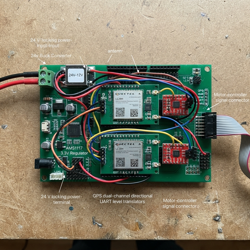
This dual GNSS RTK controller board brings centimeter-level positioning to robotics and autonomous systems by managing two independent Quectel LC29H RTK modules on a single ESP32-S3 platform. The board accepts 24 V input, distributes regulated 3.3 V power across multiple branches, and routes dual GNSS antenna signals through SMA connectors while handling serial communication via level-translated UART interfaces.
Builders will receive a complete wiring diagram, detailed parts list, assembly sequence with inspection checkpoints, and Arduino firmware that initializes both GPS receivers at 115200 baud, manages CAN bus communication, and logs data to microSD card. The guide covers power distribution, antenna routing, UART translation, and motor control signal integration, with step-by-step instructions designed to ensure reliable RTK performance before applying main power.
Wiring diagram

Gather all the parts
Assemble it in 8 steps
1. Place the power-input parts
Fit power_input_24v, buck_24v_to_5v, and controller_3v3_regulator at the board edge. Keep the 24 V input tracks wide and short, and place the buck converter’s input and output capacitors immediately beside its pins so supply spikes stay away from the rest of the board.
- Mark the terminal clearly: +24V and GND.
- Use a locking two-position terminal rated above 24 V.
- Do not connect 24 V to any 5 V or 3.3 V net — that can immediately damage the ESP32 and GPS modules.
2. Build the three 3.3 V supply branches
Fit gps1_ldo and gps2_ldo with the capacitors required by their regulator datasheets. Route each regulator output only to its own LC29H module first, then connect all grounds to one solid ground plane. This gives each receiver its own cleaner supply branch even though they share the 24 V input.
- Place each GPS regulator and its capacitors close to the module it powers.
- Keep the switching buck converter and its inductor as far as practical from both GPS modules and antenna connectors.
- Make sure VCC and GND are not swapped on either GPS module — swapped power can damage the receiver.
3. Route both GPS antenna paths
Place gps1_antenna_connector and gps2_antenna_connector at a board edge. Route each connector directly to its matching LC29H RF_IN pin as a controlled 50-ohm track, with no branches and a continuous ground reference underneath. Keep the two RF tracks apart and away from the buck converter, motor connector, and fast digital tracks.
- Follow the LC29H reference layout for the RF matching network and antenna keep-out area.
- Use active GNSS antennas only if the selected LC29H antenna circuit includes the required bias feed and protection parts.
- Do not run a GPS RF track under or beside the buck converter inductor — electrical noise can prevent accurate position fixes.
4. Wire the GPS serial translators
Fit gps1_uart_level_shifter and gps2_uart_level_shifter between the ESP32-S3 and the GPS modules. Connect GPS 1 through GPIO5 and GPIO4, and GPS 2 through GPIO7 and GPIO6. The translator’s low-voltage side uses each LC29H VDD_EXT reference, while its other side uses the ESP32 3.3 V rail; this prevents 3.3 V logic from being forced into the GPS module’s 2.8 V serial pins.
- Keep each UART pair short and route each pair together.
- Check the translator direction pins against the schematic before ordering the PCB: GPS TX must reach ESP32 RX, and ESP32 TX must reach GPS RX.
- Do not bypass the level translators — a direct 3.3 V ESP32 output can overstress the LC29H’s 2.8 V serial input.
5. Fit the UART comparison connector
Fit esp32_serial_connector as a three-position connector: TX to GPIO15 (data), RX to GPIO16 (data), and GND to the ground plane (ground). At the second ESP32, cross the two data wires: this board’s TX goes to its RX, and this board’s RX goes to its TX.
- Keep this cable short and away from motor wires.
- Label TX, RX, and GND on both boards.
- Only connect it to 3.3 V UART pins — a 5 V serial signal can damage the ESP32.
6. Fit the CAN comparison connector
Fit can_transceiver and can_connector. Connect GPIO21 to the transceiver TX input (data), GPIO14 to its RX output (data), VCC to 3V3 (power), and GND to GND (ground). Connect CANH and CANL from the transceiver to the matching CANH and CANL terminals on can_connector; connect the connector GND to GND (ground). Fit can_termination_resistor across CANH and CANL only when this board is at one physical end of the CAN cable.
- Use a twisted pair for CANH and CANL.
- Use the same CAN speed, 500 kbit/s, on the other ESP32 during the comparison.
- Do not connect CANH or CANL directly to an ESP32 GPIO — the transceiver is the protective translator between the chip and the cable.
- Install exactly two 120-ohm termination resistors in the whole CAN cable, one at each physical end; extra resistors make the signal weaker.
7. Fit the microSD card socket
Fit microsd_storage near the ESP32-S3, but away from the GPS antenna area and the buck converter. Connect 3V to 3V3 (power), GND to GND (ground), CLK to GPIO12 (clock), MISO to GPIO13 (data from card), MOSI to GPIO11 (data to card), and CS to GPIO10 (card select). Insert a FAT32-formatted microSD card only after the board has been checked for correct 3.3 V power.
- Keep CLK, MISO, MOSI, and CS short and route them over an unbroken ground plane.
- Use a 3.3 V-only socket or breakout; the selected design has no 5 V protection.
- Never connect the microSD 3V pin to the 5 V rail — 5 V can damage the card and its socket electronics.
- Do not insert or remove the card while the board is powered unless the final firmware explicitly supports safe removal.
8. Fit the motor connector and inspect before applying 24 V
Fit motor_controller_connector as a three-position connector: SIG1 to GPIO17 (signal), SIG2 to GPIO18 (signal), and GND to the ground plane (ground). Before connecting 24 V, use a multimeter to check that +24V is not shorted to GND, then check that the buck output is 5 V and the three regulator outputs are 3.3 V. Only then install the ESP32-S3 and GPS modules, attach antennas, insert the microSD card, and connect external cables.
- The firmware holds both motor signals low whenever the ESP32 starts.
- Power up without the GPS modules installed first if you can; it makes a wiring mistake easier to find.
- Only connect the motor-controller connector to a controller confirmed to accept 3.3 V logic — a higher-voltage signal on GPIO17 or GPIO18 can damage the ESP32.
- Never probe or move connector wiring while the 24 V supply is connected — a slipped probe can short the supply and damage PCB tracks.
Review all connections
1. Connections between "power_input_24v" and "ESP32"
2. Connections between "buck_24v_to_5v" and "ESP32"
3. Connections between "gps1_ldo" and "ESP32"
4. Connections between "gps2_ldo" and "ESP32"
5. Connections between "lc29h_1" and "ESP32"
6. Connections between "lc29h_2" and "ESP32"
7. Connections between "gps1_uart_level_shifter" and "ESP32"
8. Connections between "gps2_uart_level_shifter" and "ESP32"
9. Connections between "gps1_antenna_connector" and "ESP32"
10. Connections between "gps2_antenna_connector" and "ESP32"
11. Connections between "motor_controller_connector" and "ESP32"
12. Connections between "esp32_serial_connector" and "ESP32"
13. Connections between "controller_3v3_regulator" and "ESP32"
14. Connections between "can_transceiver" and "ESP32"
15. Connections between "can_termination_resistor" and "ESP32"
16. Connections between "can_connector" and "ESP32"
17. Connections between "microsd_storage" and "ESP32"
Deploy the firmware
#include <Arduino.h>
#include <SPI.h>
#include <SD.h>
#include <driver/twai.h>

void setupCan();
void setupStorage();

constexpr int GPS1_RX_PIN = 5;
constexpr int GPS1_TX_PIN = 4;
constexpr int GPS2_RX_PIN = 7;
constexpr int GPS2_TX_PIN = 6;
constexpr int PEER_ESP32_RX_PIN = 16;
constexpr int PEER_ESP32_TX_PIN = 15;
constexpr int MOTOR_SIG1_PIN = 17;
constexpr int MOTOR_SIG2_PIN = 18;
constexpr int CAN_RX_PIN = 14;
constexpr int CAN_TX_PIN = 21;
constexpr int SD_CS_PIN = 10;
constexpr int SD_MOSI_PIN = 11;
constexpr int SD_SCK_PIN = 12;
constexpr int SD_MISO_PIN = 13;

constexpr uint32_t GPS_BAUD = 115200;
constexpr uint32_t PEER_BAUD = 115200;

HardwareSerial gps1Serial(1);
HardwareSerial gps2Serial(2);
HardwareSerial peerSerial(0);

bool canStarted = false;
bool storageReady = false;

void setupCan() {
  twai_general_config_t generalConfig = TWAI_GENERAL_CONFIG_DEFAULT(
      static_cast<gpio_num_t>(CAN_TX_PIN), static_cast<gpio_num_t>(CAN_RX_PIN), TWAI_MODE_NORMAL);
  twai_timing_config_t timingConfig = TWAI_TIMING_CONFIG_500KBITS();
  twai_filter_config_t filterConfig = TWAI_FILTER_CONFIG_ACCEPT_ALL();

  if (twai_driver_install(&generalConfig, &timingConfig, &filterConfig) == ESP_OK) {
    canStarted = (twai_start() == ESP_OK);
  }
}

void setupStorage() {
  SPI.begin(SD_SCK_PIN, SD_MISO_PIN, SD_MOSI_PIN, SD_CS_PIN);
  storageReady = SD.begin(SD_CS_PIN, SPI);
}

void setup() {
  pinMode(MOTOR_SIG1_PIN, OUTPUT);
  pinMode(MOTOR_SIG2_PIN, OUTPUT);
  digitalWrite(MOTOR_SIG1_PIN, LOW);
  digitalWrite(MOTOR_SIG2_PIN, LOW);

  gps1Serial.begin(GPS_BAUD, SERIAL_8N1, GPS1_RX_PIN, GPS1_TX_PIN);
  gps2Serial.begin(GPS_BAUD, SERIAL_8N1, GPS2_RX_PIN, GPS2_TX_PIN);
  peerSerial.begin(PEER_BAUD, SERIAL_8N1, PEER_ESP32_RX_PIN, PEER_ESP32_TX_PIN);
  setupCan();
  setupStorage();
}

void loop() {
  // GPS streams remain independent. UART and CAN are available for comparison.
  // storageReady becomes true only when a formatted microSD card is installed.
  if (canStarted) {
    twai_message_t message = {};
    if (twai_receive(&message, pdMS_TO_TICKS(1)) == ESP_OK) {
      // Application-specific CAN message handling belongs here.
    }
  }
  delay(10);
}
Remix this project
Make it yours in one click
Open a full copy of this project in your own Schematik workspace — diagram, code, parts, and assembly steps included. Swap the sensor, add features, or redesign the whole thing with AI. The author's original stays untouched.