Community project
ESP32 NeoPixel Light Control
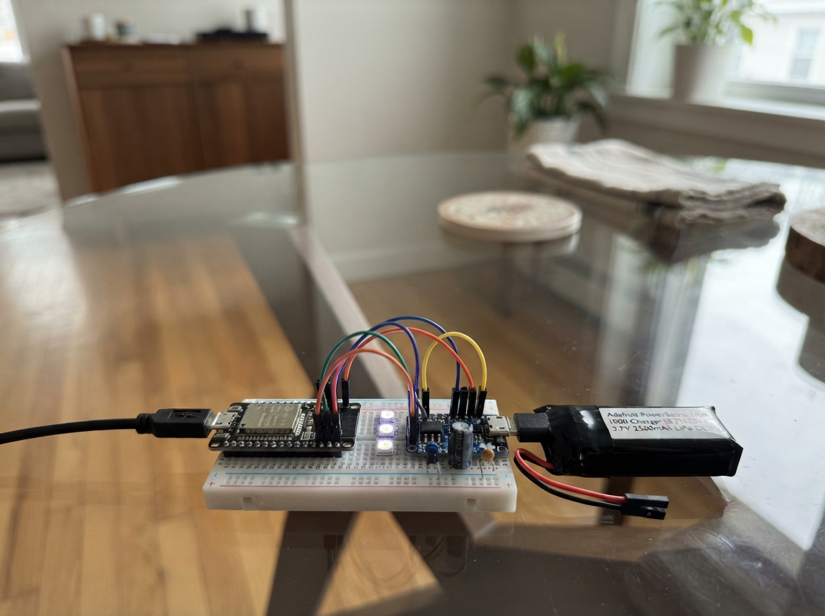
Build a WiFi-controlled RGB light using an ESP32 microcontroller and a 7-pixel NeoPixel ring. This project combines a rechargeable lithium battery with a boost charger to create a portable light that can display solid colors, rainbow animations, or turn off completely via a web interface.
The guide includes a complete parts list, wiring diagram showing proper connections through the level shifter and power management circuit, and ready-to-use Arduino firmware with WiFi access point mode. Follow the assembly steps to solder components in the right order, connect the power system with correct polarity, and have a functioning networked light ready to customize and extend.
Wiring diagram

Gather all the parts
Assemble it in 5 steps
1. Order the carrier PCB and parts
Make a small custom carrier PCB with labeled sockets or through-holes for the ESP32 DevKit v1, PowerBoost 1000, NeoPixel Jewel, 74AHCT125, 330 Ω resistor, 1000 µF capacitor, and 0.1 µF ceramic capacitor. Keep the PowerBoost USB charging socket and the ESP32 USB socket at the board edge so their cables still fit.
- Use wider copper paths for every 5 V and GND connection to the Jewel because the LEDs can draw short bursts of current.
- Print clear labels beside BAT, 5V, GND, DIN, and the capacitor plus sign; these make assembly much less error-prone.
- This is a carrier PCB for plug-in modules, not a board for soldering a bare ESP32 chip or a bare lithium charger circuit. Do not copy battery charging circuits unless they have been professionally designed and tested.
2. Solder the small parts first
Solder the 74AHCT125, the 330 Ω resistor, and the 0.1 µF ceramic capacitor first. Put the 74AHCT125 notch in the same direction as the notch mark printed on the PCB. Place the 0.1 µF capacitor immediately beside the chip’s VCC and GND connections; either ceramic-capacitor lead may go in either hole.
- Use a low-power iron and inspect for solder bridges between neighboring 74AHCT125 pins before adding power.
- The 330 Ω resistor has no positive or negative side.
- A backwards 74AHCT125 or a solder bridge can damage the chip when power is applied.
3. Fit the power parts with the right polarity
Solder the 1000 µF capacitor close to the NeoPixel Jewel 5 V and GND pads: its long positive lead, marked +, goes to 5 V, and its striped negative lead goes to GND. Mount the PowerBoost and connect its 5V output to the PCB 5 V rail and its GND output to the PCB ground rail. Connect the battery BAT+ lead only to PowerBoost BAT and BAT- only to PowerBoost GND.
- Use red wire or a red PCB label for 5 V and black for ground.
- Before inserting the ESP32 or Jewel, use a multimeter to confirm the PCB rail is about 5 V and that 5 V is not shorted to GND.
- Swapping the large capacitor or battery polarity can make a part hot, leak, or fail. Never connect the battery directly to the 5 V rail, ESP32, or NeoPixel Jewel.
4. Install the ESP32 and LED board
Fit the ESP32 DevKit and NeoPixel Jewel into their labeled sockets or solder pads. Connect the PCB 5 V rail to ESP32 5V/VIN and Jewel VCC, and connect the PCB ground rail to ESP32 GND and Jewel GND. On the data path, ESP32 GPIO 18 goes to 74AHCT125 1A (signal), 74AHCT125 1OE goes to GND (keeps that channel on), 1Y goes to one end of the 330 Ω resistor (signal protection), and the resistor’s other end goes to Jewel DIN (color-control signal).
- Use the Jewel pad labeled DIN; DOUT is only for adding another LED board later.
- Keep the 74AHCT125, resistor, and Jewel DIN trace short and away from the PowerBoost switching area.
- Never route the 74AHCT125 5 V output back to GPIO 18 — 5 V on an ESP32 input can damage the board. Do not put the PowerBoost 5 V rail on the ESP32 3V3 pin.
5. Charge and use the finished light
Put the PCB in a non-conductive case with openings for both USB sockets and with no pressure on the battery wires. Charge through the PowerBoost USB socket on a hard, non-flammable surface. Plug the ESP32 USB socket into your computer, press Deploy in Schematik, join ESP32-Light with password lightcontrol, then open 192.168.4.1 in a browser.
- Your phone may say the ESP32-Light network has no internet; stay connected because the control page is stored in the light.
- At the normal starting brightness, the battery should run the light for roughly 15 to 20 hours; higher brightness makes the run time shorter.
- Stop using the battery immediately if it becomes swollen, damaged, unusually hot, or smells strange. Do not leave lithium battery charging unattended.
Review all connections
1. Connections between "level_shifter" and "ESP32"
2. Connections between "data_resistor" and "ESP32"
3. Connections between "neopixel_jewel" and "ESP32"
4. Connections between "battery" and "ESP32"
5. Connections between "powerboost" and "ESP32"
6. Connections between "bulk_capacitor" and "ESP32"
7. Connections between "decoupling_capacitor" and "ESP32"
Deploy the firmware
#include <Arduino.h>
#include <WiFi.h>
#include <WebServer.h>
#include <Adafruit_NeoPixel.h>

uint32_t wheel(byte position);
void showSolid();
void showRainbow();
bool parseHexColor(const String &text, uint32_t &color);
void handleRoot();
void handleSet();
void handleRainbow();
void handleOff();

constexpr uint8_t NEOPIXEL_PIN = 18;
constexpr uint8_t PIXEL_COUNT = 7;
constexpr char AP_NAME[] = "ESP32-Light";
constexpr char AP_PASSWORD[] = "lightcontrol";

Adafruit_NeoPixel pixels(PIXEL_COUNT, NEOPIXEL_PIN, NEO_GRB + NEO_KHZ800);
WebServer server(80);

uint8_t brightness = 48;
uint32_t selectedColor = 0xFFFFFF;
bool rainbowEnabled = true;
uint16_t rainbowOffset = 0;
unsigned long lastFrameMs = 0;

uint32_t wheel(byte position) {
  position = 255 - position;
  if (position < 85) return pixels.Color(255 - position * 3, 0, position * 3);
  if (position < 170) {
    position -= 85;
    return pixels.Color(0, position * 3, 255 - position * 3);
  }
  position -= 170;
  return pixels.Color(position * 3, 255 - position * 3, 0);
}

void showSolid() {
  pixels.setBrightness(brightness);
  pixels.fill(selectedColor);
  pixels.show();
}

void showRainbow() {
  pixels.setBrightness(brightness);
  for (uint8_t pixel = 0; pixel < PIXEL_COUNT; ++pixel) {
    byte hue = (pixel * 256 / PIXEL_COUNT + rainbowOffset) & 0xFF;
    pixels.setPixelColor(pixel, wheel(hue));
  }
  pixels.show();
}

bool parseHexColor(const String &text, uint32_t &color) {
  if (text.length() != 7 || text[0] != '#') return false;
  char *endPointer;
  unsigned long value = strtoul(text.substring(1).c_str(), &endPointer, 16);
  if (*endPointer != '\0') return false;
  color = value;
  return true;
}

void handleRoot() {
  const char page[] PROGMEM = R"HTML(<!doctype html><html><head><meta name="viewport" content="width=device-width,initial-scale=1"><style>body{font-family:Arial;text-align:center;background:#171717;color:#fff;margin:0;padding:28px}main{max-width:360px;margin:auto}input,button{width:100%;box-sizing:border-box;margin:12px 0;height:48px;border-radius:8px;border:0;font-size:18px}button{background:#38a8ff;color:#fff;font-weight:bold}input[type=color]{padding:3px}p{color:#ccc}</style></head><body><main><h1>ESP32 Light</h1><p>Choose a color or start the rainbow.</p><input id="color" type="color" value="#ffffff"><input id="level" type="range" min="0" max="255" value="48"><button onclick="solid()">Set color</button><button onclick="fetch('/rainbow')">Start rainbow</button><button onclick="fetch('/off')">Turn off</button><p id="status"></p></main><script>function solid(){fetch('/set?color='+encodeURIComponent(color.value)+'&brightness='+level.value).then(r=>r.text()).then(t=>status.textContent=t)}color.oninput=()=>{rainbow=false};level.onchange=solid;</script></body></html>)HTML";
  server.send(200, "text/html", page);
}

void handleSet() {
  uint32_t newColor;
  if (!server.hasArg("color") || !parseHexColor(server.arg("color"), newColor)) {
    server.send(400, "text/plain", "Use a color such as #ff0000.");
    return;
  }
  selectedColor = newColor;
  if (server.hasArg("brightness")) brightness = constrain(server.arg("brightness").toInt(), 0, 255);
  rainbowEnabled = false;
  showSolid();
  server.send(200, "text/plain", "Color set.");
}

void handleRainbow() {
  rainbowEnabled = true;
  server.send(200, "text/plain", "Rainbow started.");
}

void handleOff() {
  rainbowEnabled = false;
  pixels.clear();
  pixels.show();
  server.send(200, "text/plain", "Lights off.");
}

void setup() {
  pixels.begin();
  pixels.clear();
  pixels.show();

  WiFi.mode(WIFI_AP);
  WiFi.softAP(AP_NAME, AP_PASSWORD);
  server.on("/", handleRoot);
  server.on("/set", handleSet);
  server.on("/rainbow", handleRainbow);
  server.on("/off", handleOff);
  server.begin();
  showRainbow();
}

void loop() {
  server.handleClient();
  if (rainbowEnabled && millis() - lastFrameMs >= 50) {
    lastFrameMs = millis();
    ++rainbowOffset;
    showRainbow();
  }
}
Remix this project
Make it yours in one click
Open a full copy of this project in your own Schematik workspace — diagram, code, parts, and assembly steps included. Swap the sensor, add features, or redesign the whole thing with AI. The author's original stays untouched.