Community project
ESP32 Servo Control
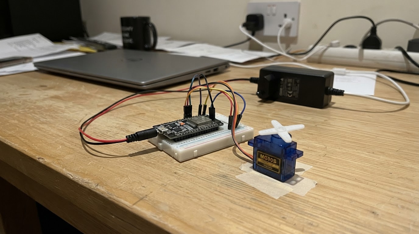
This project builds an autonomous rover that uses an ESP32 microcontroller and camera to capture images, send them to a vision AI service, and respond with servo-controlled movements. The rover interprets AI responses (FORWARD, BACKWARD, LEFT, RIGHT, STOP, WIGGLE) to navigate autonomously, making it ideal for exploring obstacle courses or following visual cues.
The guide provides a complete wiring diagram showing how to connect two MG90S micro servos to the ESP32 for differential drive control, a parts list including the regulated 5V power supply required for reliable servo operation, and step-by-step assembly instructions for preparing the rover chassis and setting mechanical neutral. Firmware code is included with WiFi and secure vision-AI integration, allowing the rover to make real-time decisions based on camera input.
Wiring diagram

Gather all the parts
Assemble it in 4 steps
1. Prepare the rover chassis
Mount the two continuous-rotation servos on opposite sides of a small chassis with their output shafts facing outward. Attach one wheel to each servo horn and add a low-friction rear skid or caster. Place the ESP32-CAM so its camera looks forward and has an unobstructed view.
- Label the left and right servo before wiring; these labels assume forward is in the camera direction.
- Keep the camera clear of wheels, wires, and the chassis edge.
- Do not let the rover operate near a desk edge, stairs, liquids, or loose cables. The camera-only design cannot reliably detect every hazard.
2. Distribute the regulated 5 V power
With the 5 V supply unplugged, connect its 5V OUT to both servo red/VCC wires and to the ESP32-CAM 5V pin. Connect its GND OUT to both servo brown/black GND wires and to an ESP32-CAM GND pin. This common ground connection is required for reliable servo control.
- Use short, adequately thick power wiring for the servo supply.
- A 5 V supply rated at 3 A or more is required; the servos can cause high startup current.
- Never power the servos from the ESP32-CAM 3.3 V pin or from a weak USB adapter.
- Check polarity carefully: reversed 5 V and GND can permanently damage the ESP32-CAM and servos.
3. Connect the two servo signal wires
Connect the left servo SIG wire (usually orange/yellow/white) to ESP32-CAM GPIO16. Connect the right servo SIG wire to ESP32-CAM GPIO17. Do not connect either signal wire to the 5 V rail.
- GPIO16 and GPIO17 are the safe available outputs when the built-in camera is in use.
- Keep signal wires away from the camera ribbon and high-current motor wiring where practical.
- Do not use camera-reserved pins for servo signals; doing so prevents the OV2640 camera from operating.
4. Power-on and set mechanical neutral
Lift the wheels off the desk, then power the regulated 5 V supply. The firmware initially commands a 1500 microsecond neutral pulse, so both wheels should remain stopped. If a wheel creeps, adjust that continuous-rotation servo's physical neutral trim screw. If a wheel moves backward when commanded forward later, reverse that servo mechanically or swap its direction terms in firmware.
- Perform neutral adjustment before allowing it to drive on the desk.
- The ESP32-CAM must be flashed through Schematik's Deploy button after you enter Wi-Fi and relay details in the firmware.
- Keep fingers away from the wheels during this test.
- The supplied firmware intentionally remains stopped until valid Wi-Fi and secure relay settings are entered.
Review all connections
1. Connections between "servo_power_supply" and "ESP32"
2. Connections between "left_drive_servo" and "ESP32"
3. Connections between "right_drive_servo" and "ESP32"
Deploy the firmware
#include <Arduino.h>
#include <WiFi.h>
#include <WiFiClientSecure.h>
#include <HTTPClient.h>
#include <ESP32Servo.h>
#include "esp_camera.h"

// Enter Wi-Fi details and the URL of your secure vision-AI relay.
// The relay receives a JPEG and returns one word: STOP, FORWARD, BACKWARD, LEFT, RIGHT, or WIGGLE.
// Keep any AI-provider API key on that relay, never on this rover.

// Forward declarations
void stopDrive();
void driveFor(const String &action, uint32_t durationMs);
String actionFromReply(const String &reply);
bool connectWiFi();
String askVisionAI(camera_fb_t *frame);
bool initCamera();

static const char *WIFI_SSID = "YOUR_WIFI_NAME";
static const char *WIFI_PASSWORD = "YOUR_WIFI_PASSWORD";
static const char *VISION_ENDPOINT = "https://YOUR-SECURE-VISION-RELAY.example/analyze";

static const int LEFT_SERVO_PIN = 16;
static const int RIGHT_SERVO_PIN = 17;
static const int STOP_US = 1500;
static const int DRIVE_OFFSET_US = 115;
static const uint32_t OBSERVE_INTERVAL_MS = 6000;
static const uint32_t MAX_MOVE_MS = 350;

#define PWDN_GPIO_NUM 32
#define RESET_GPIO_NUM -1
#define XCLK_GPIO_NUM 0
#define SIOD_GPIO_NUM 26
#define SIOC_GPIO_NUM 27
#define Y9_GPIO_NUM 35
#define Y8_GPIO_NUM 34
#define Y7_GPIO_NUM 39
#define Y6_GPIO_NUM 36
#define Y5_GPIO_NUM 21
#define Y4_GPIO_NUM 19
#define Y3_GPIO_NUM 18
#define Y2_GPIO_NUM 5
#define VSYNC_GPIO_NUM 25
#define HREF_GPIO_NUM 23
#define PCLK_GPIO_NUM 22

Servo leftServo;
Servo rightServo;
uint32_t lastObservationMs = 0;

void stopDrive() {
  leftServo.writeMicroseconds(STOP_US);
  rightServo.writeMicroseconds(STOP_US);
}

void driveFor(const String &action, uint32_t durationMs) {
  int leftPulse = STOP_US;
  int rightPulse = STOP_US;
  if (action == "FORWARD") { leftPulse += DRIVE_OFFSET_US; rightPulse -= DRIVE_OFFSET_US; }
  else if (action == "BACKWARD") { leftPulse -= DRIVE_OFFSET_US; rightPulse += DRIVE_OFFSET_US; }
  else if (action == "LEFT") { leftPulse -= DRIVE_OFFSET_US; rightPulse -= DRIVE_OFFSET_US; }
  else if (action == "RIGHT") { leftPulse += DRIVE_OFFSET_US; rightPulse += DRIVE_OFFSET_US; }
  else if (action == "WIGGLE") {
    leftServo.writeMicroseconds(STOP_US + DRIVE_OFFSET_US);
    rightServo.writeMicroseconds(STOP_US + DRIVE_OFFSET_US);
    delay(durationMs / 2);
    leftServo.writeMicroseconds(STOP_US - DRIVE_OFFSET_US);
    rightServo.writeMicroseconds(STOP_US - DRIVE_OFFSET_US);
    delay(durationMs / 2);
    stopDrive();
    return;
  } else { stopDrive(); return; }
  leftServo.writeMicroseconds(leftPulse);
  rightServo.writeMicroseconds(rightPulse);
  delay(durationMs);
  stopDrive();
}

String actionFromReply(const String &reply) {
  const char *actions[] = {"STOP", "FORWARD", "BACKWARD", "LEFT", "RIGHT", "WIGGLE"};
  for (uint8_t i = 0; i < 6; i++) if (reply.indexOf(actions[i]) >= 0) return String(actions[i]);
  return "STOP";
}

bool connectWiFi() {
  if (WiFi.status() == WL_CONNECTED) return true;
  if (String(WIFI_SSID).startsWith("YOUR_")) return false;
  WiFi.mode(WIFI_STA);
  WiFi.begin(WIFI_SSID, WIFI_PASSWORD);
  uint32_t started = millis();
  while (WiFi.status() != WL_CONNECTED && millis() - started < 15000) delay(250);
  return WiFi.status() == WL_CONNECTED;
}

String askVisionAI(camera_fb_t *frame) {
  if (!connectWiFi() || String(VISION_ENDPOINT).indexOf("YOUR-") >= 0) return "STOP";
  WiFiClientSecure client;
  client.setInsecure();
  HTTPClient http;
  if (!http.begin(client, VISION_ENDPOINT)) return "STOP";
  http.addHeader("Content-Type", "image/jpeg");
  http.addHeader("X-Rover-Prompt", "You are Curio, a playful curious desk rover. Inspect the image and reply exactly with one safe action: STOP, FORWARD, BACKWARD, LEFT, RIGHT, or WIGGLE. Prefer STOP. Never move toward people, hands, desk edges, stairs, cables, cups, or uncertainty. Movement is capped at 350 ms.");
  int status = http.POST(frame->buf, frame->len);
  String response = status == HTTP_CODE_OK ? http.getString() : "STOP";
  http.end();
  return actionFromReply(response);
}

bool initCamera() {
  camera_config_t config = {};
  config.ledc_channel = LEDC_CHANNEL_0; config.ledc_timer = LEDC_TIMER_0;
  config.pin_d0 = Y2_GPIO_NUM; config.pin_d1 = Y3_GPIO_NUM; config.pin_d2 = Y4_GPIO_NUM; config.pin_d3 = Y5_GPIO_NUM;
  config.pin_d4 = Y6_GPIO_NUM; config.pin_d5 = Y7_GPIO_NUM; config.pin_d6 = Y8_GPIO_NUM; config.pin_d7 = Y9_GPIO_NUM;
  config.pin_xclk = XCLK_GPIO_NUM; config.pin_pclk = PCLK_GPIO_NUM; config.pin_vsync = VSYNC_GPIO_NUM; config.pin_href = HREF_GPIO_NUM;
  config.pin_sccb_sda = SIOD_GPIO_NUM; config.pin_sccb_scl = SIOC_GPIO_NUM; config.pin_pwdn = PWDN_GPIO_NUM; config.pin_reset = RESET_GPIO_NUM;
  config.xclk_freq_hz = 20000000; config.pixel_format = PIXFORMAT_JPEG; config.frame_size = FRAMESIZE_QVGA;
  config.jpeg_quality = 14; config.fb_count = 1;
  return esp_camera_init(&config) == ESP_OK;
}

void setup() {
  Serial.begin(115200);
  leftServo.setPeriodHertz(50); rightServo.setPeriodHertz(50);
  leftServo.attach(LEFT_SERVO_PIN, 500, 2500); rightServo.attach(RIGHT_SERVO_PIN, 500, 2500);
  stopDrive();
  if (!initCamera()) Serial.println("Camera failed; rover remains stopped.");
}

void loop() {
  if (millis() - lastObservationMs < OBSERVE_INTERVAL_MS) return;
  lastObservationMs = millis();
  camera_fb_t *frame = esp_camera_fb_get();
  if (frame == nullptr) { stopDrive(); return; }
  String action = askVisionAI(frame);
  esp_camera_fb_return(frame);
  Serial.printf("Curio chose: %s\n", action.c_str());
  driveFor(action, MAX_MOVE_MS);
}
Remix this project
Make it yours in one click
Open a full copy of this project in your own Schematik workspace — diagram, code, parts, and assembly steps included. Swap the sensor, add features, or redesign the whole thing with AI. The author's original stays untouched.