Community project
Un Syst De Contr Le Et De Gestion
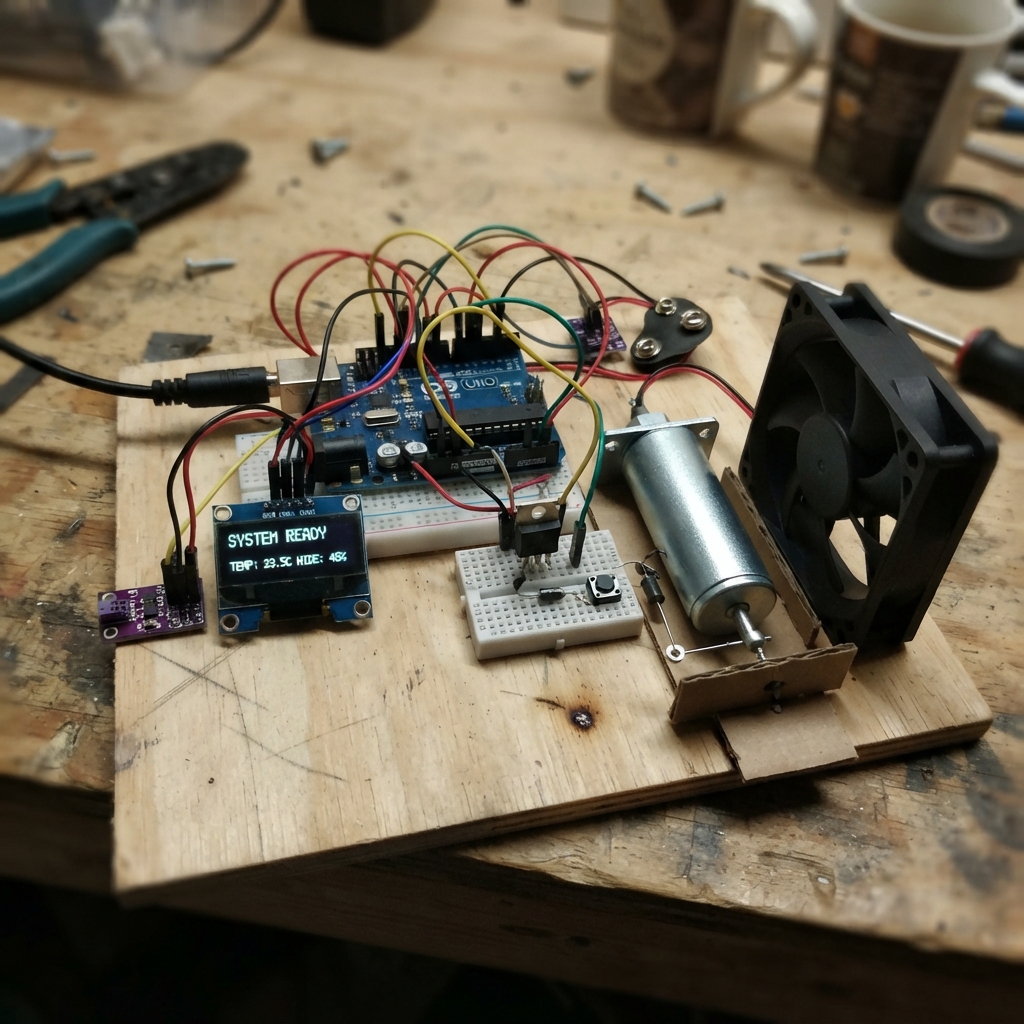
This control and management system monitors temperature and humidity while automatically managing a fan and solenoid-driven feeder. Built around an ESP32 microcontroller, it combines an AHT20 climate sensor with an SSD1306 OLED display to show real-time conditions, and uses MOSFETs to switch a 12V PC fan and solenoid feeder based on temperature thresholds or manual button activation.
The guide provides a complete wiring diagram, full parts list with specifications, and step-by-step assembly instructions from power preparation through pre-power verification. Included firmware handles automatic fan control, manual feeder triggering with debouncing, and display updates, ready to upload directly to the ESP32.
Wiring diagram

Gather all the parts
Assemble it in 6 steps
1. Préparer l’alimentation hors tension
Laissez l’adaptateur 12 V débranché du secteur. Réglez d’abord le petit convertisseur MP1584 à exactement 5,0 V avec un multimètre, puis reliez sa sortie 5 V au VIN de l’ESP32 et sa sortie GND au GND de l’ESP32. Reliez également le GND de l’adaptateur 12 V au GND commun : tous les éléments doivent partager ce retour électrique.
- Mesurez la sortie du convertisseur avant de brancher l’ESP32 ; une tension supérieure à 5 V peut endommager la carte.
- Ne branchez jamais le 12 V directement sur une broche 3V3, VIN ou GND de l’ESP32 : cela peut détruire la carte.
2. Brancher le capteur et le petit écran
Reliez le capteur AHT20 et l’écran OLED aux mêmes quatre rangées : VIN/VCC vers 3V3 (alimentation), GND vers GND (retour électrique), SDA vers GPIO21 (données) et SCL vers GPIO22 (horloge).
- Le capteur et l’écran peuvent partager GPIO21 et GPIO22 ; ce sont les deux fils de communication communs.
- Placez le capteur à hauteur des poulets, à l’écart du souffle direct du ventilateur et de l’eau.
- Assurez-vous que VCC/VIN et GND ne sont pas inversés : une alimentation inversée peut endommager le capteur ou l’écran.
3. Câbler le bouton de distribution
Placez le bouton à cheval sur la fente centrale de la plaque d’essai. Reliez une patte à GPIO27 (signal) et la patte opposée à GND (retour électrique).
- Un appui lance une distribution de cinq secondes ; le programme évite qu’un appui bref soit compté plusieurs fois.
- Ne reliez pas le bouton au 12 V : GPIO27 accepte seulement les petits signaux 3,3 V de l’ESP32.
4. Monter le circuit du ventilateur
Reliez le fil positif 12V du ventilateur au +12V de l’adaptateur (alimentation). Reliez son fil GND au drain du MOSFET, puis la source du MOSFET au GND commun (interrupteur électronique). Placez la diode 1N4007 en parallèle sur le ventilateur : côté avec bague vers +12V et côté sans bague vers le fil GND du ventilateur. Reliez GPIO25 à la grille du MOSFET à travers la résistance 220 Ω, puis reliez une résistance 10 kΩ entre cette grille et GND. Reliez enfin l’entrée PWM séparée du ventilateur à GPIO32 (commande de vitesse).
- La diode et la résistance 10 kΩ doivent être proches du MOSFET.
- Le fil PWM n’existe que sur un ventilateur PC à quatre fils ; avec un ventilateur à deux fils, laissez cette connexion absente et conservez la commande marche/arrêt par le MOSFET.
- La bague de la diode doit être du côté +12 V ; si elle est inversée, la diode peut chauffer et endommager l’alimentation.
5. Monter la commande de la mangeoire
Reliez le VCC de l’électroaimant 12 V au +12V de l’adaptateur (alimentation). Reliez son GND au drain du second MOSFET, puis la source de ce MOSFET au GND commun (interrupteur électronique). Placez la seconde diode 1N4007 sur l’électroaimant : côté avec bague vers +12V et côté sans bague vers son GND. Reliez GPIO26 à la grille par la résistance 220 Ω, puis mettez la résistance 10 kΩ entre la grille et GND.
- Fixez l’électroaimant et sa tringlerie pour qu’ils ne puissent pas coincer les animaux.
- Testez sans aliment ni mécanisme lourd lors du premier appui sur le bouton.
- L’électroaimant peut chauffer et pincer ; gardez les doigts, les câbles souples et les animaux hors de sa course.
6. Vérifier avant la première mise sous tension
Vérifiez une dernière fois que tous les GND sont communs, que les diodes ont leur bague vers le +12V et qu’aucun fil 12 V n’arrive sur l’ESP32. Branchez ensuite l’ESP32 par USB et l’adaptateur 12 V séparément.
- L’écran doit afficher la température et l’humidité quelques secondes après le démarrage.
- Le ventilateur démarre à 29 °C et s’arrête à 27 °C ; le bouton fait fonctionner la mangeoire pendant cinq secondes.
- Utilisez uniquement un ventilateur, un électroaimant et un adaptateur 12 V CC. Pour des appareils secteur, des chauffages ou de gros moteurs, faites installer un contacteur et les protections appropriées par un électricien qualifié.
Review all connections
1. Connections between "climate_sensor" and "ESP32"
2. Connections between "status_oled" and "ESP32"
3. Connections between "fan_mosfet" and "ESP32"
4. Connections between "feeder_mosfet" and "ESP32"
5. Connections between "fan" and "ESP32"
6. Connections between "fan_diode" and "ESP32"
7. Connections between "feeder_solenoid" and "ESP32"
8. Connections between "feeder_diode" and "ESP32"
9. Connections between "feed_button" and "ESP32"
10. Connections between "dc_supply" and "ESP32"
11. Connections between "buck_5v" and "ESP32"
12. Connections between "fan_gate_resistor" and "ESP32"
13. Connections between "feeder_gate_resistor" and "ESP32"
14. Connections between "fan_gate_pulldown" and "ESP32"
15. Connections between "feeder_gate_pulldown" and "ESP32"
Deploy the firmware
#include <Arduino.h>
#include <Wire.h>
#include <Adafruit_AHTX0.h>
#include <Adafruit_GFX.h>
#include <Adafruit_SSD1306.h>


// Forward declarations
void setFan(bool enabled);
void setFeeder(bool enabled);
void drawStatus(const char *message);
void readClimateAndControl();
void handleFeedButton();

constexpr int FAN_POWER_PIN = 25;
constexpr int FEEDER_PIN = 26;
constexpr int FEED_BUTTON_PIN = 27;
constexpr int FAN_PWM_PIN = 32;
constexpr int I2C_SDA_PIN = 21;
constexpr int I2C_SCL_PIN = 22;

constexpr uint8_t SCREEN_WIDTH = 128;
constexpr uint8_t SCREEN_HEIGHT = 64;
constexpr uint8_t OLED_ADDRESS = 0x3C;
constexpr float FAN_ON_TEMP_C = 29.0f;
constexpr float FAN_OFF_TEMP_C = 27.0f;
constexpr unsigned long SENSOR_INTERVAL_MS = 2000;
constexpr unsigned long FEED_DURATION_MS = 5000;
constexpr unsigned long BUTTON_DEBOUNCE_MS = 40;
constexpr uint8_t FAN_PWM_CHANNEL = 0;

Adafruit_AHTX0 aht;
Adafruit_SSD1306 display(SCREEN_WIDTH, SCREEN_HEIGHT, &Wire, -1);

bool sensorReady = false;
bool displayReady = false;
bool fanOn = false;
bool feederOn = false;
bool lastRawButton = HIGH;
bool stableButton = HIGH;
unsigned long lastButtonChangeMs = 0;
unsigned long feederStartMs = 0;
unsigned long lastSensorMs = 0;
float lastTemperature = NAN;
float lastHumidity = NAN;

void setFan(bool enabled) {
  fanOn = enabled;
  digitalWrite(FAN_POWER_PIN, enabled ? HIGH : LOW);
}

void setFeeder(bool enabled) {
  feederOn = enabled;
  digitalWrite(FEEDER_PIN, enabled ? HIGH : LOW);
  if (enabled) feederStartMs = millis();
}

void drawStatus(const char *message) {
  if (!displayReady) return;

  display.clearDisplay();
  display.setTextColor(SSD1306_WHITE);
  display.setTextSize(1);
  display.setCursor(0, 0);
  display.println("FERME AVICOLE");
  display.drawLine(0, 10, 127, 10, SSD1306_WHITE);

  display.setCursor(0, 16);
  if (sensorReady && !isnan(lastTemperature)) {
    display.print("Temp: ");
    display.print(lastTemperature, 1);
    display.println(" C");
    display.print("Hum.: ");
    display.print(lastHumidity, 0);
    display.println(" %");
  } else {
    display.println("Capteur indisponible");
  }

  display.setCursor(0, 42);
  display.print("Ventilation: ");
  display.println(fanOn ? "MARCHE" : "ARRET");
  display.print("Mangeoire: ");
  display.println(feederOn ? "MARCHE" : "PRETE");
  if (message != nullptr) {
    display.setCursor(0, 56);
    display.print(message);
  }
  display.display();
}

void readClimateAndControl() {
  if (!sensorReady) {
    drawStatus("Verifier AHT20");
    return;
  }

  sensors_event_t humidityEvent;
  sensors_event_t temperatureEvent;
  aht.getEvent(&humidityEvent, &temperatureEvent);
  if (isnan(temperatureEvent.temperature) || isnan(humidityEvent.relative_humidity)) {
    drawStatus("Lecture capteur echouee");
    return;
  }

  lastTemperature = temperatureEvent.temperature;
  lastHumidity = humidityEvent.relative_humidity;
  if (!fanOn && lastTemperature >= FAN_ON_TEMP_C) setFan(true);
  else if (fanOn && lastTemperature <= FAN_OFF_TEMP_C) setFan(false);
  drawStatus(nullptr);
}

void handleFeedButton() {
  const bool rawButton = digitalRead(FEED_BUTTON_PIN);
  const unsigned long now = millis();
  if (rawButton != lastRawButton) {
    lastButtonChangeMs = now;
    lastRawButton = rawButton;
  }
  if ((now - lastButtonChangeMs) >= BUTTON_DEBOUNCE_MS && rawButton != stableButton) {
    stableButton = rawButton;
    if (stableButton == LOW && !feederOn) {
      setFeeder(true);
      drawStatus("Distribution en cours");
    }
  }
  if (feederOn && now - feederStartMs >= FEED_DURATION_MS) {
    setFeeder(false);
    drawStatus("Distribution terminee");
  }
}

void setup() {
  pinMode(FAN_POWER_PIN, OUTPUT);
  pinMode(FEEDER_PIN, OUTPUT);
  pinMode(FEED_BUTTON_PIN, INPUT_PULLUP);
  digitalWrite(FAN_POWER_PIN, LOW);
  digitalWrite(FEEDER_PIN, LOW);

  ledcSetup(FAN_PWM_CHANNEL, 25000, 8);
  ledcAttachPin(FAN_PWM_PIN, FAN_PWM_CHANNEL);
  ledcWrite(FAN_PWM_CHANNEL, 255);

  Wire.begin(I2C_SDA_PIN, I2C_SCL_PIN);
  displayReady = display.begin(SSD1306_SWITCHCAPVCC, OLED_ADDRESS);
  sensorReady = aht.begin();
  drawStatus(sensorReady ? "Demarrage" : "AHT20 absent");
}

void loop() {
  handleFeedButton();
  const unsigned long now = millis();
  if (now - lastSensorMs >= SENSOR_INTERVAL_MS) {
    lastSensorMs = now;
    readClimateAndControl();
  }
}
Remix this project
Make it yours in one click
Open a full copy of this project in your own Schematik workspace — diagram, code, parts, and assembly steps included. Swap the sensor, add features, or redesign the whole thing with AI. The author's original stays untouched.