Community project
ESP32 Stabilized Drone
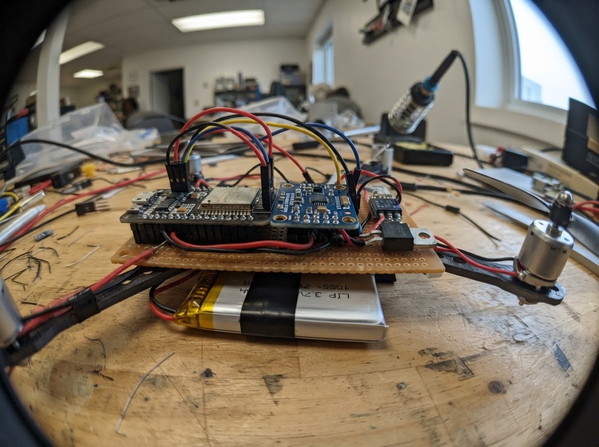
This guide builds a small quadcopter stabilized by an ESP32 microcontroller and MPU-6050 inertial measurement unit. The drone uses four N20 micro metal gear motors driven by IRF540N MOSFETs, powered by a 3.7V LiPo battery with regulated 3.3V logic supply. Builders will receive a complete wiring diagram, parts list, and step-by-step assembly instructions for the guarded X-frame airframe.
The firmware implements gyroscope calibration, roll and pitch stabilization via PID control, and WiFi command reception over a local access point. The guide includes a propeller-off bench test procedure and tuning notes for motor idle throttle. Readers will learn how to integrate IMU sensor data with motor control on the ESP32 platform and understand the feedback loop that keeps the drone level in flight.
Wiring diagram

Gather all the parts
Assemble it in 5 steps
1. Prepare the guarded X-frame
Use a light 65–75 mm micro-quadcopter frame with four prop guards. Mount each 8520 motor in its arm. Mark the front of the frame and keep the ESP32-C3 antenna clear of carbon, battery, and motor wiring.
- Fit matched CW/CCW propeller pairs only after all electrical testing.
- Keep total take-off mass very low; this design has limited thrust margin.
- Never run an unguarded propeller indoors.
2. Build the motor switching stage
For each motor, connect its M+ terminal to raw LiPo positive and its M− terminal to that motor's AO3400A drain. Connect every AO3400A source to LiPo negative. Between each ESP32 PWM output and its MOSFET gate fit a 100 ohm resistor, and fit a 100k resistor from each gate to source. Fit an SS14 or 1N5819 flyback diode across each motor: striped cathode to M+, unstriped anode to M−.
- Use a MOSFET explicitly specified for low RDS(on) at 2.5–3.3 V gate drive, such as AO3400A; do not substitute the large IRF540N named by the generic catalog reference.
- Keep motor-current loops short and use adequately thick wire.
- A missing diode, gate pulldown, or common ground can cause uncontrolled motor operation or damage the ESP32.
- Do not connect the LiPo until you have inspected for shorts with a meter.
3. Wire the controller and IMU
Connect FL, FR, RR, and RL MOSFET gates (through their 100 ohm resistors) to GPIO0, GPIO1, GPIO2, and GPIO3 respectively. Connect MPU-6050 VIN to regulated 3.3 V, GND to common ground, SDA to GPIO8, and SCL to GPIO9. Mount the IMU flat, centered, and aligned with the frame front; vibration-isolate it lightly with foam tape.
- The IMU must use 3.3 V I²C logic.
- Use the same battery-negative ground for boost regulator, ESP32, IMU, and all motor MOSFET sources.
- GPIO9 is also the board boot-button pin; do not hold it low at power-up.
4. Wire battery and regulated logic power
Connect LiPo positive to the raw motor-positive rail and to boost VIN. Connect LiPo negative to the common ground rail and boost GND. Set and verify the boost regulator output at exactly 3.3 V before connecting it to the ESP32-C3 3V3 pin and MPU-6050 VIN.
- Use a 1S 300 mAh LiPo capable of at least 9 A burst current.
- Charge the LiPo only after disconnecting it from the quadcopter, using a suitable 1S LiPo balance charger.
- Never connect raw 1S LiPo directly to the ESP32 3V3 pin.
- Stop using a swollen, damaged, hot, or deeply discharged LiPo.
5. Perform a propeller-off test
Remove all propellers. Place the frame perfectly level and power it up without moving it for about two seconds so the IMU gyro calibrates. Connect a phone to Wi-Fi network LearningQuad using password fly-safely, then open http://192.168.4.1. Confirm each slider changes only its intended motor response, then disarm and correct motor direction/propeller placement before fitting props.
- The controller stops the motors if it loses phone commands for about 0.35 seconds.
- First hover tests should be just above a clear floor, with a second person ready to disconnect the battery.
- Keep fingers, faces, pets, loose clothing, and bystanders clear whenever the battery is connected.
- This is a learning controller: begin at very low throttle and tune only in a clear, enclosed indoor space.
Review all connections
1. Connections between "battery" and "ESP32"
2. Connections between "boost" and "ESP32"
3. Connections between "imu" and "ESP32"
4. Connections between "motor_fl" and "ESP32"
5. Connections between "motor_fr" and "ESP32"
6. Connections between "motor_rr" and "ESP32"
7. Connections between "motor_rl" and "ESP32"
8. Connections between "fet_fl" and "ESP32"
9. Connections between "fet_fr" and "ESP32"
10. Connections between "fet_rr" and "ESP32"
11. Connections between "fet_rl" and "ESP32"
Deploy the firmware
#include <Arduino.h>
#include <Wire.h>
#include <WiFi.h>
#include <WebServer.h>

// Propellers MUST be removed for first power-up and IMU calibration.
#define MOTOR_FL_PIN 0
#define MOTOR_FR_PIN 1
#define MOTOR_RR_PIN 2
#define MOTOR_RL_PIN 3
#define IMU_SDA_PIN 8
#define IMU_SCL_PIN 9


// Forward declarations
void writeMotor(uint8_t pin, int value);
void stopMotors();
bool mpuWrite(uint8_t reg, uint8_t value);
bool readImu(float &ax, float &ay, float &az, float &gx, float &gy, float &gz);
bool initializeImu();
bool calibrateGyro();
void handleSet();

static const char *AP_NAME = "LearningQuad";
static const char *AP_PASSWORD = "fly-safely";
static const uint8_t MPU_ADDR = 0x68;
static const uint32_t PWM_FREQUENCY = 16000;
static const uint8_t PWM_RESOLUTION = 8;
static const int MOTOR_MAX = 210;       // leaves headroom below full battery drive
static const int MOTOR_IDLE = 58;       // tune upward only after guarded bench test
static const uint32_t COMMAND_TIMEOUT_MS = 350;

WebServer server(80);
volatile bool armed = false;
float commandThrottle = 0.0f;
float commandRoll = 0.0f;
float commandPitch = 0.0f;
float commandYaw = 0.0f;
uint32_t lastCommandMs = 0;

float gyroXBias = 0, gyroYBias = 0, gyroZBias = 0;
float rollDeg = 0, pitchDeg = 0;
float rollI = 0, pitchI = 0;
float lastRollError = 0, lastPitchError = 0;
uint32_t lastLoopUs = 0;

void writeMotor(uint8_t pin, int value) {
  value = constrain(value, 0, MOTOR_MAX);
  ledcWrite(pin, value);
}

void stopMotors() {
  writeMotor(MOTOR_FL_PIN, 0);
  writeMotor(MOTOR_FR_PIN, 0);
  writeMotor(MOTOR_RR_PIN, 0);
  writeMotor(MOTOR_RL_PIN, 0);
}

bool mpuWrite(uint8_t reg, uint8_t value) {
  Wire.beginTransmission(MPU_ADDR);
  Wire.write(reg);
  Wire.write(value);
  return Wire.endTransmission() == 0;
}

bool readImu(float &ax, float &ay, float &az, float &gx, float &gy, float &gz) {
  Wire.beginTransmission(MPU_ADDR);
  Wire.write(0x3B);
  if (Wire.endTransmission(false) != 0 || Wire.requestFrom((int)MPU_ADDR, 14) != 14) return false;
  int16_t rawAx = (Wire.read() << 8) | Wire.read();
  int16_t rawAy = (Wire.read() << 8) | Wire.read();
  int16_t rawAz = (Wire.read() << 8) | Wire.read();
  Wire.read(); Wire.read();
  int16_t rawGx = (Wire.read() << 8) | Wire.read();
  int16_t rawGy = (Wire.read() << 8) | Wire.read();
  int16_t rawGz = (Wire.read() << 8) | Wire.read();
  ax = rawAx / 16384.0f;
  ay = rawAy / 16384.0f;
  az = rawAz / 16384.0f;
  gx = rawGx / 131.0f;
  gy = rawGy / 131.0f;
  gz = rawGz / 131.0f;
  return true;
}

bool initializeImu() {
  Wire.beginTransmission(MPU_ADDR);
  if (Wire.endTransmission() != 0) return false;
  return mpuWrite(0x6B, 0x00) && mpuWrite(0x1B, 0x00) && mpuWrite(0x1C, 0x00);
}

bool calibrateGyro() {
  const int samples = 600;
  float ax, ay, az, gx, gy, gz;
  gyroXBias = gyroYBias = gyroZBias = 0;
  for (int i = 0; i < samples; ++i) {
    if (!readImu(ax, ay, az, gx, gy, gz)) return false;
    gyroXBias += gx;
    gyroYBias += gy;
    gyroZBias += gz;
    delay(3);
  }
  gyroXBias /= samples;
  gyroYBias /= samples;
  gyroZBias /= samples;
  return true;
}

const char CONTROL_PAGE[] PROGMEM = R"HTML(
<!doctype html><html><meta name=viewport content='width=device-width,initial-scale=1'>
<style>body{font-family:sans-serif;max-width:520px;margin:auto;background:#10131a;color:#eee;padding:16px}input{width:100%}button{padding:12px;margin:6px;font-size:16px}.warn{color:#ffcf55}</style>
<h2>LearningQuad control</h2><p class=warn>Keep clear of propellers. Arm only on a clear floor.</p>
<button onclick='arm(1)'>ARM</button><button onclick='arm(0)'>DISARM</button><p id=s>disarmed</p>
<label>Throttle <input id=t type=range min=0 max=100 value=0></label><br><label>Roll <input id=r type=range min=-25 max=25 value=0></label><br><label>Pitch <input id=p type=range min=-25 max=25 value=0></label><br><label>Yaw <input id=y type=range min=-30 max=30 value=0></label>
<script>let a=0;function arm(x){a=x;fetch('/set?arm='+x);document.querySelector('#s').textContent=x?'ARMED':'disarmed'}setInterval(()=>fetch(`/set?thr=${t.value}&roll=${r.value}&pitch=${p.value}&yaw=${y.value}&arm=${a}`),100);</script></html>
)HTML";

void handleSet() {
  if (server.hasArg("arm")) armed = server.arg("arm").toInt() == 1;
  if (server.hasArg("thr")) commandThrottle = constrain(server.arg("thr").toFloat(), 0.0f, 100.0f);
  if (server.hasArg("roll")) commandRoll = constrain(server.arg("roll").toFloat(), -25.0f, 25.0f);
  if (server.hasArg("pitch")) commandPitch = constrain(server.arg("pitch").toFloat(), -25.0f, 25.0f);
  if (server.hasArg("yaw")) commandYaw = constrain(server.arg("yaw").toFloat(), -30.0f, 30.0f);
  lastCommandMs = millis();
  if (!armed) stopMotors();
  server.send(200, "text/plain", armed ? "armed" : "disarmed");
}

void setup() {
  Serial.begin(115200);
  ledcAttach(MOTOR_FL_PIN, PWM_FREQUENCY, PWM_RESOLUTION);
  ledcAttach(MOTOR_FR_PIN, PWM_FREQUENCY, PWM_RESOLUTION);
  ledcAttach(MOTOR_RR_PIN, PWM_FREQUENCY, PWM_RESOLUTION);
  ledcAttach(MOTOR_RL_PIN, PWM_FREQUENCY, PWM_RESOLUTION);
  stopMotors();
  Wire.begin(IMU_SDA_PIN, IMU_SCL_PIN);
  Wire.setClock(400000);
  if (!initializeImu()) Serial.println("MPU6050 not found; motors remain disabled.");
  else if (!calibrateGyro()) Serial.println("MPU6050 calibration failed; motors remain disabled.");
  WiFi.mode(WIFI_AP);
  WiFi.softAP(AP_NAME, AP_PASSWORD);
  Serial.print("Control page: http://");
  Serial.println(WiFi.softAPIP());
  server.on("/", [](){ server.send_P(200, "text/html", CONTROL_PAGE); });
  server.on("/set", handleSet);
  server.begin();
  lastCommandMs = millis();
  lastLoopUs = micros();
}

void loop() {
  server.handleClient();
  uint32_t nowUs = micros();
  if (nowUs - lastLoopUs < 4000) return; // 250 Hz control loop
  float dt = (nowUs - lastLoopUs) * 0.000001f;
  lastLoopUs = nowUs;

  float ax, ay, az, gx, gy, gz;
  bool imuOk = readImu(ax, ay, az, gx, gy, gz);
  if (!imuOk || millis() - lastCommandMs > COMMAND_TIMEOUT_MS) {
    armed = false;
    stopMotors();
    return;
  }
  gx -= gyroXBias; gy -= gyroYBias; gz -= gyroZBias;
  float accelRoll = atan2f(ay, az) * 57.29578f;
  float accelPitch = atan2f(-ax, sqrtf(ay * ay + az * az)) * 57.29578f;
  rollDeg = 0.98f * (rollDeg + gx * dt) + 0.02f * accelRoll;
  pitchDeg = 0.98f * (pitchDeg + gy * dt) + 0.02f * accelPitch;

  if (!armed || commandThrottle < 1.0f) {
    rollI = pitchI = 0;
    stopMotors();
    return;
  }

  const float KP = 3.2f, KI = 0.22f, KD = 0.09f;
  float rollError = commandRoll - rollDeg;
  float pitchError = commandPitch - pitchDeg;
  rollI = constrain(rollI + rollError * dt, -25.0f, 25.0f);
  pitchI = constrain(pitchI + pitchError * dt, -25.0f, 25.0f);
  float rollCorrection = KP * rollError + KI * rollI + KD * (rollError - lastRollError) / dt;
  float pitchCorrection = KP * pitchError + KI * pitchI + KD * (pitchError - lastPitchError) / dt;
  lastRollError = rollError; lastPitchError = pitchError;
  float base = MOTOR_IDLE + commandThrottle * (MOTOR_MAX - MOTOR_IDLE) / 100.0f;
  float yawCorrection = commandYaw * 0.7f;
  // FL/RR are CW; FR/RL are CCW. Reverse a motor's two leads if its rotation does not match the frame marking.
  writeMotor(MOTOR_FL_PIN, (int)(base + pitchCorrection + rollCorrection - yawCorrection));
  writeMotor(MOTOR_FR_PIN, (int)(base + pitchCorrection - rollCorrection + yawCorrection));
  writeMotor(MOTOR_RR_PIN, (int)(base - pitchCorrection - rollCorrection - yawCorrection));
  writeMotor(MOTOR_RL_PIN, (int)(base - pitchCorrection + rollCorrection + yawCorrection));
}
Remix this project
Make it yours in one click
Open a full copy of this project in your own Schematik workspace — diagram, code, parts, and assembly steps included. Swap the sensor, add features, or redesign the whole thing with AI. The author's original stays untouched.