Schematik build
Four-Wheel RC Car Wiring
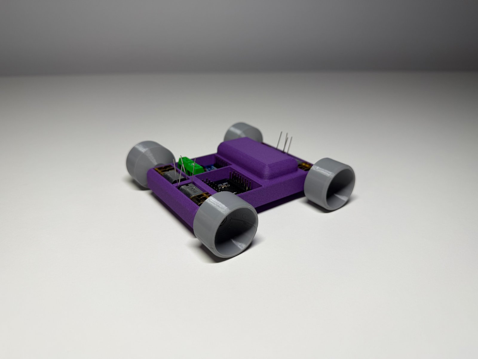
Build a WiFi-controlled four-wheel RC car powered by an ESP32 microcontroller. This project combines a LiPo battery, buck-boost converter, L9110S motor driver, and four geared DC motors to create a nimble platform that responds to web commands over a local access point.
The guide provides a complete wiring diagram showing power distribution, motor driver connections, and decoupling capacitor placement for clean operation. Builders will receive a parts list, step-by-step assembly instructions, and ready-to-flash firmware that hosts a web interface for forward, backward, left, and right control.
Wiring diagram

Gather all the parts
Assemble it in 6 steps
1. Prepare the power wiring
With the LiPo disconnected, wire battery +V (red, marked +) to the IN terminal of power_switch. Wire power_switch OUT as the switched-LiPo-positive junction. From this same OUT junction, run one wire to l9110s_1 VCC and one wire to buckboost_3v3 VIN. Wire lipo_1s GND (black, marked −), buckboost_3v3 GND, l9110s_1 GND, and the ESP32 GND pin into one common-ground junction.
- Use heavier, short wire for the battery, switch, driver VCC, and ground paths because motor current flows there.
- A star-like common-ground junction near the L9110S/battery return helps reduce motor noise.
- Observe LiPo polarity. A reversed LiPo can destroy the converter and driver.
- Do not connect the raw LiPo positive lead directly to the LOLIN S2 Mini 3V3 pin.
- This parts list has no charging circuit: charge the protected LiPo only with a proper single-cell LiPo charger, disconnected from the car if the charger requires it.
2. Set and connect the 3.3 V converter
Before connecting the ESP32, power the switched input from the LiPo and use a multimeter to set buckboost_3v3 VOUT to exactly 3.3 V. Switch power off, then connect VOUT to the LOLIN S2 Mini 3V3 pin and leave its GND connected to the common-ground junction from step 1. Fit esp_decoupling_cap directly between the ESP32 3V3 and GND pins.
- Keep the 100 nF ceramic capacitor leads very short.
- If the chosen converter has an EN pin that must be driven high, follow its module markings; many modules already tie EN high.
- Check 3.3 V with a meter before the ESP32 is attached. Never feed more than 3.3 V into its 3V3 pin.
3. Add driver supply filtering and logic wiring
Fit motor_bulk_cap close to l9110s_1: capacitor + to L9110S VCC and capacitor − to common ground. Observe its stripe-marked negative lead. Connect LOLIN S2 Mini GPIO9 to L9110S A-IA, GPIO10 to A-IB, GPIO11 to B-IA, and GPIO12 to B-IB. The driver and ESP32 grounds must remain common.
- Keep the four GPIO control wires away from motor wires where possible.
- The 470 µF electrolytic should be rated at least 6.3 V; 10 V or higher is also suitable.
- The 470 µF capacitor is polarized: its negative-striped lead goes only to GND.
- Do not use GPIO9–GPIO12 for another function in this build.
4. Wire channel A to both left motors
Make a parallel pair from L9110S channel A: connect A-OUT1 to left_front_motor M+ and left_rear_motor M+. Connect A-OUT2 to left_front_motor M− and left_rear_motor M−. Solder lf_motor_cap directly across the left-front motor terminals and lr_motor_cap directly across the left-rear motor terminals.
- The two branch junctions at A-OUT1 and A-OUT2 are the required parallel connection for the left side.
- Place each 100 nF capacitor physically on its motor terminals, not back at the driver.
- The combined stall current of the left-front and left-rear motors must remain within the L9110S channel-current rating. Do not estimate from running current alone; use stall-current data or measure it.
5. Wire channel B to both right motors
Make a parallel pair from L9110S channel B: connect B-OUT1 to right_front_motor M+ and right_rear_motor M+. Connect B-OUT2 to right_front_motor M− and right_rear_motor M−. Solder rf_motor_cap across the right-front motor terminals and rr_motor_cap across the right-rear motor terminals.
- Keep left and right motor-pair wiring similar in length and thickness.
- Secure motor leads so vibration cannot fatigue the solder joints.
- The combined stall current of the right-front and right-rear motors must remain within the L9110S channel-current rating. If either pair overloads the driver, use lower-current motors or a higher-current driver.
6. Check rotation and operate the car
Raise the car so all wheels are clear, turn on power, and use Schematik’s Deploy button to flash the firmware. On a phone, join Wi‑Fi network S2-RC-Car using password drivecar, then open http://192.168.4.1. Press Forward briefly. If one wheel turns opposite to the other wheel on the same side, switch off power and reverse only that motor’s two wires; keep its 100 nF capacitor across its two terminals.
- Test while the wheels are off the bench first.
- If forward/reverse is swapped for all four wheels, swap the forward/reverse logic in firmware rather than rewiring every motor.
- Keep fingers, loose wires, and clothing clear of spinning wheels.
- Stop immediately if the L9110S becomes very hot, the battery protection trips, or the ESP32 resets when accelerating.
Review all connections
1. Connections between "lipo_1s" and "ESP32"
2. Connections between "power_switch" and "ESP32"
3. Connections between "buckboost_3v3" and "ESP32"
4. Connections between "l9110s_1" and "ESP32"
5. Connections between "motor_bulk_cap" and "ESP32"
6. Connections between "esp_decoupling_cap" and "ESP32"
7. Connections between "lf_motor_cap" and "ESP32"
8. Connections between "lr_motor_cap" and "ESP32"
9. Connections between "rf_motor_cap" and "ESP32"
10. Connections between "rr_motor_cap" and "ESP32"
Deploy the firmware
#include <Arduino.h>
#include <WiFi.h>
#include <WebServer.h>

#define LEFT_IA_PIN 9
#define LEFT_IB_PIN 10
#define RIGHT_IA_PIN 11
#define RIGHT_IB_PIN 12


// Forward declarations
void stopCar();
void setLeft(bool forward);
void setRight(bool forward);
void handleCommand();
void handleRoot();

const char *AP_SSID = "S2-RC-Car";
const char *AP_PASSWORD = "drivecar";

WebServer server(80);

void stopCar() {
  digitalWrite(LEFT_IA_PIN, LOW);
  digitalWrite(LEFT_IB_PIN, LOW);
  digitalWrite(RIGHT_IA_PIN, LOW);
  digitalWrite(RIGHT_IB_PIN, LOW);
}

void setLeft(bool forward) {
  digitalWrite(LEFT_IA_PIN, forward ? HIGH : LOW);
  digitalWrite(LEFT_IB_PIN, forward ? LOW : HIGH);
}

void setRight(bool forward) {
  digitalWrite(RIGHT_IA_PIN, forward ? HIGH : LOW);
  digitalWrite(RIGHT_IB_PIN, forward ? LOW : HIGH);
}

void handleCommand() {
  String command = server.arg("c");

  if (command == "forward") {
    setLeft(true);
    setRight(true);
  } else if (command == "back") {
    setLeft(false);
    setRight(false);
  } else if (command == "left") {
    setLeft(false);
    setRight(true);
  } else if (command == "right") {
    setLeft(true);
    setRight(false);
  } else {
    stopCar();
  }

  server.send(200, "text/plain", "OK");
}

void handleRoot() {
  const char page[] = R"rawliteral(
<!doctype html><html><head><meta name="viewport" content="width=device-width,initial-scale=1">
<style>body{font-family:sans-serif;text-align:center;background:#151515;color:#fff;margin:0;padding:24px}button{width:120px;height:68px;margin:7px;font-size:20px;border:0;border-radius:10px;background:#2574d9;color:#fff}button.stop{background:#c93636}</style>
</head><body><h2>ESP32-S2 RC Car</h2><p>Hold a direction button to drive; releasing it stops the car.</p>
<div><button data-c="forward">Forward</button></div><div><button data-c="left">Left</button><button data-c="right">Right</button></div><div><button data-c="back">Reverse</button></div><div><button class="stop" data-c="stop">STOP</button></div>
<script>document.querySelectorAll('button').forEach(b=>{const go=()=>fetch('/cmd?c='+b.dataset.c);b.onpointerdown=go;b.onpointerup=()=>fetch('/cmd?c=stop');b.onpointerleave=()=>fetch('/cmd?c=stop');b.onpointercancel=()=>fetch('/cmd?c=stop');});</script>
</body></html>
)rawliteral";
  server.send(200, "text/html", page);
}

void setup() {
  pinMode(LEFT_IA_PIN, OUTPUT);
  pinMode(LEFT_IB_PIN, OUTPUT);
  pinMode(RIGHT_IA_PIN, OUTPUT);
  pinMode(RIGHT_IB_PIN, OUTPUT);
  stopCar();

  WiFi.mode(WIFI_AP);
  WiFi.softAP(AP_SSID, AP_PASSWORD);

  server.on("/", HTTP_GET, handleRoot);
  server.on("/cmd", HTTP_GET, handleCommand);
  server.begin();
}

void loop() {
  server.handleClient();
}
Download project files
Remix this project
Make it yours in one click
Open a full copy of this project in your own Schematik workspace — diagram, code, parts, and assembly steps included. Swap the sensor, add features, or redesign the whole thing with AI. The author's original stays untouched.
Related projects
How to Build a Self-Balancing Rover with ESP32
ESP32 · Intermediate · 60 minutes · July 22, 2026Schematik
How to Build an ESP32 Plane Radar
ESP32 · Intermediate · 1.5 hours · June 12, 2026Schematik
How to Build a Pocket GPS Dashboard
ESP32 · Intermediate · 45 minutes · July 22, 2026Schematik