Schematik build
How to Build a Self-Balancing Rover with ESP32
IMU-based stabilization with live battery and tilt stats on OLED
What you'll build
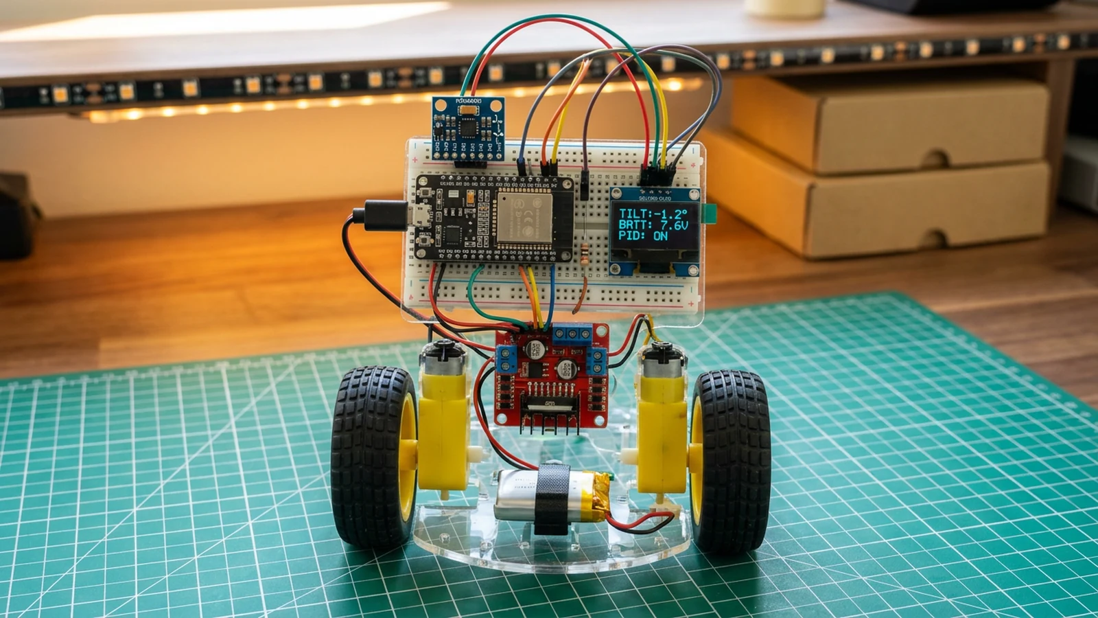
This guide builds a self-balancing two-wheeled rover: an ESP32 reads tilt from an MPU6050 IMU, feeds the angle into a PID control loop, and drives two DC gear motors through an L298N H-bridge to keep the chassis upright. A small SSD1306 OLED displays live tilt angle, battery voltage, and the three PID gain values so you can watch the control system at work without opening a serial monitor.
PID control is one of the most important concepts in robotics. A self-balancing robot is the classic way to develop intuition for it because the feedback is immediate and physical: you can see the rover overshoot, oscillate, or drift and directly connect that behaviour to specific gain values. The build also covers reading raw accelerometer data over I2C, converting it to an orientation angle with atan2, and managing two motor channels with PWM through ledcAttach.
The same MPU6050 used here also appears in the fitness wristband, where accelerometer data drives step counting rather than balance control.
What you are building
The firmware has four main jobs:
- Read accelerometer and gyroscope events from the MPU6050 over I2C (SDA GPIO21, SCL GPIO22) and combine them in a complementary tilt filter,
- Run a PID loop at roughly 100 Hz, with integral clamping and a 35° tip-over cutoff that immediately locks the motors off,
- Drive the L298N via four PWM channels on GPIO25 (IN1), GPIO26 (IN2), GPIO32 (IN3), GPIO33 (IN4) using
ledcAttachat 5 kHz / 8-bit resolution, - Read battery voltage from the voltage divider on GPIO36 (BATT_PIN, input-only) and refresh the SSD1306 OLED every loop cycle with angle, control output, battery voltage, and the current
kp,ki,kdvalues.
Remote control, obstacle avoidance, and multi-mode driving are outside the scope of this build.
Upload and calibrate
Open the project in Schematik and click Deploy using Chrome or Edge. Once uploaded, open Serial Monitor at 115200 baud. You should see Rover ready within a second of boot.
Stand the rover upright by hand and read the tilt angle on the OLED. If your IMU is not perfectly vertical on the chassis, note the resting angle and set targetAngle to that value instead of 0.0.
The three gain constants in the firmware are:
kp— proportional gain, currently 24.0: controls the immediate response to tilt. Too low and the rover falls; too high and it oscillates.ki— integral gain, currently 0.4: corrects slow drift. Keep this small untilkpandkdare stable.kd— derivative gain, currently 0.85: damps rapid changes. Increase this if the rover oscillates at a fixed frequency.
Start with ki = 0 and kd = 0 and raise kp until the rover reacts but oscillates. Then add kd to damp the oscillation. Add a small ki last to remove any steady-state lean. Expect to iterate several times; the right values depend on your motor gear ratio, wheel radius, and chassis weight distribution.
Troubleshooting
- OLED stays blank: confirm I2C address is
0x3C. Some SSD1306 modules use0x3D. Both devices share the bus, so if one is wrong the whole I2C bus may lock. - MPU6050 not found on boot: Serial Monitor prints "MPU6050 not found" if the library cannot reach the sensor. Check SDA/SCL wiring and confirm the module has power. The default I2C address is
0x68; if AD0 is pulled high it becomes0x69. - Motors spin in the wrong direction: swap the two wires on one motor terminal, or invert the IN1/IN2 (or IN3/IN4) logic in
driveMotors(). Both corrections work; changing the code is cleaner for a permanent build. - Rover falls immediately without balancing: the PID gains need tuning for your specific chassis weight. Start with
kp = 24,ki = 0,kd = 0and place the rover on a flat surface; if it tries to correct but oscillates, addkd. If it barely reacts, raisekp. - Battery voltage reads wrong: check that the top leg is three 100 kΩ resistors in series, the lower leg is one 100 kΩ resistor, and their junction goes to GPIO36. The firmware multiplier is
4.0; change it only if you deliberately use a different measured divider ratio. - Motors stop after the rover tips: this is the 35° safety cutoff. Return the chassis upright before the controller can drive again.
- ESP32 resets during motor starts: the motor supply and the ESP32 must share a common GND. If they are isolated, inductive spikes from the motors can reset or damage the board.
Scaling to a full platform
Once balance is reliable, the motor PWM outputs can be modulated by a remote-control input — Bluetooth serial is the easiest addition on this hardware. Replacing the single-axis atan2 angle estimate with the MPU6050's built-in DMP (digital motion processor) gives a more stable orientation reading under vibration. An ultrasonic sensor on the front mirrors the parking-sensor build and adds obstacle awareness without changing the balance logic.
Wiring diagram
Gather all the parts
Assemble it in 4 steps
1. Build the I2C control stack
Connect the MPU6050 and SSD1306 to ESP32 3.3 V and GND, with SDA on GPIO21 and SCL on GPIO22. Mount the MPU6050 rigidly near the chassis centreline so its pitch axis matches the wheel axle.
- Keep I2C wires under 15 cm.
- Do not mount the IMU on loose foam or flexible wires.
2. Wire motors and the regulated logic supply
Connect L298N IN1–IN4 to GPIO25, GPIO26, GPIO32 and GPIO33. Feed the L298N motor rail directly from the 8×AA holder loaded with eight matched NiMH cells. Feed the same battery into the MP1584, adjust its output to exactly 5.0 V with a multimeter before connecting the ESP32, then connect MP1584 OUT+ to ESP32 VIN/5V and OUT− to GND. Join battery, MP1584, L298N and ESP32 grounds. Leave the L298N ENA and ENB jumpers installed so both bridges stay enabled while firmware applies PWM to IN1–IN4. Insulate the chassis encoder leads individually; this starter does not use them.
- Test motor direction with the chassis lifted clear of the bench.
- Do not use the L298N 5 V regulator output to power the ESP32.
- Do not connect the battery to an ESP32 GPIO or 3.3 V pin.
3. Add the protected battery monitor
Make the upper divider leg from three 100 kΩ resistors in series between battery positive and the sense node. Put one 100 kΩ resistor from the sense node to ground, then connect the sense node to input-only GPIO36. The 4:1 divider keeps a fresh 8×AA NiMH pack below the ESP32 ADC limit and matches the 4.0 multiplier in firmware.
- Measure the sense node before connecting GPIO36; it must stay below 3.3 V.
- GPIO36 is input-only. Never drive it as an output.
4. Upload and tune the balance loop
Flash the sketch with the wheels lifted. Confirm tilt direction, motor direction and battery reading first. Start with proportional gain only, add derivative damping, then a small integral term while keeping the firmware integral clamp enabled.
- Tune on a clear floor with the rover tethered loosely.
- Keep a hand on the power switch during first balancing tests.
Review all connections
1. Connections between "battery-divider-resistors" and "ESP32"
2. Connections between "motor-driver-1" and "ESP32"
3. Connections between "mp1584-buck" and "ESP32"
4. Connections between "mpu6050-1" and "ESP32"
5. Connections between "oled-1" and "ESP32"
6. Connections between "rover-battery-pack-1" and "ESP32"
Deploy the firmware
#include <Wire.h>
#include <Adafruit_MPU6050.h>
#include <Adafruit_SSD1306.h>

#define SDA_PIN 21
#define SCL_PIN 22
#define IN1 25
#define IN2 26
#define IN3 32
#define IN4 33
#define BATT_PIN 36

Adafruit_MPU6050 mpu;
Adafruit_SSD1306 display(128, 64, &Wire, -1);

float targetAngle = 0.0f;
float kp = 24.0f, ki = 0.4f, kd = 0.85f;
float lastError = 0.0f;
float integral = 0.0f;
float filteredAngle = 0.0f;
bool angleInitialised = false;
bool mpuReady = false;
unsigned long lastLoopUs = 0;

void setupMotorPWM() {
  ledcAttach(IN1, 5000, 8);
  ledcAttach(IN2, 5000, 8);
  ledcAttach(IN3, 5000, 8);
  ledcAttach(IN4, 5000, 8);
}

void driveMotors(float control) {
  int pwm = constrain((int)fabs(control), 0, 255);
  bool forward = control > 0;
  ledcWrite(IN1, forward ? pwm : 0);
  ledcWrite(IN2, forward ? 0 : pwm);
  ledcWrite(IN3, forward ? pwm : 0);
  ledcWrite(IN4, forward ? 0 : pwm);
}

void setup() {
  Serial.begin(115200);
  delay(100);

  setupMotorPWM();
  driveMotors(0);

  Wire.begin(SDA_PIN, SCL_PIN);
  mpuReady = mpu.begin();
  if (!mpuReady) {
    Serial.println("MPU6050 not found; motors locked off");
  } else {
    mpu.setAccelerometerRange(MPU6050_RANGE_4_G);
    mpu.setFilterBandwidth(MPU6050_BAND_21_HZ);
  }

  display.begin(SSD1306_SWITCHCAPVCC, 0x3C);
  display.setTextSize(1);
  display.setTextColor(SSD1306_WHITE);

  pinMode(BATT_PIN, INPUT);
  lastLoopUs = micros();
  Serial.println("Rover ready");
}

void loop() {
  if (!mpuReady) {
    driveMotors(0);
    delay(100);
    return;
  }

  unsigned long nowUs = micros();
  float dt = lastLoopUs == 0 ? 0.01f : (nowUs - lastLoopUs) / 1000000.0f;
  lastLoopUs = nowUs;
  dt = constrain(dt, 0.001f, 0.05f);

  sensors_event_t a, g, t;
  mpu.getEvent(&a, &g, &t);
  float accelAngle = atan2(a.acceleration.x, a.acceleration.z) * 57.2958f;
  if (!angleInitialised) {
    filteredAngle = accelAngle;
    angleInitialised = true;
  }
  filteredAngle = 0.98f * (filteredAngle + g.gyro.y * 57.2958f * dt)
                + 0.02f * accelAngle;
  float angle = filteredAngle;
  float error = targetAngle - angle;

  integral += error * dt;
  integral = constrain(integral, -50.0f, 50.0f);
  float derivative = (error - lastError) / dt;
  float control = kp * error + ki * integral + kd * derivative;
  lastError = error;

  if (fabs(angle - targetAngle) > 35.0f) {
    driveMotors(0);
    integral = 0.0f;
  } else {
    driveMotors(control);
  }

  float battV = analogRead(BATT_PIN) / 4095.0f * 3.3f * 4.0f;

  display.clearDisplay();
  display.setCursor(0, 0);
  display.printf("Angle: %6.1f deg", angle);
  display.setCursor(0, 12);
  display.printf("Ctrl:  %6.1f", control);
  display.setCursor(0, 24);
  display.printf("Batt:  %4.2f V", battV);
  display.setCursor(0, 40);
  display.printf("P:%5.1f I:%4.1f D:%4.2f", kp, ki, kd);
  display.display();

  delay(10);
}
Remix this project
Make it yours in one click
Open a full copy of this project in your own Schematik workspace — diagram, code, parts, and assembly steps included. Swap the sensor, add features, or redesign the whole thing with AI. The author's original stays untouched.
Related projects
How to Build a Fitness Wristband Prototype with ESP32
ESP32 · Intermediate · 50 minutes · June 12, 2026Schematik
How to Build an ESP32 Kids Phone Prototype
ESP32 · Intermediate · 60 minutes · July 22, 2026Schematik
How to Build an Arcade Reaction Tower with ESP32
ESP32 · Beginner · 40 minutes · June 12, 2026Schematik