Community project
Interactive Talking Desk Buddy
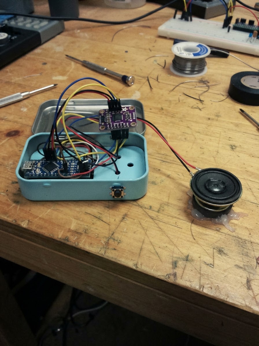
Build an interactive desk buddy that plays audio messages and displays animations on a touchscreen when you tap it. This project combines an ESP32 microcontroller with a MAX98357A Class-D amplifier and speaker to deliver clear audio output, along with a built-in display and touchscreen for interactive feedback.
This guide provides a complete parts list, wiring diagram showing all I²S audio connections, step-by-step assembly instructions, and ready-to-use firmware that handles MP3 playback from an SD card. Follow the assembly outline to connect the amplifier power, wire the I²S signals, and integrate the speaker, then load your audio files and start interacting with your desk buddy.
Wiring diagram

Gather all the parts
Assemble it in 5 steps
1. Prepare the desk-buddy parts
Gather the ESP32-2432S028R board, a MAX98357A I²S amplifier breakout (audio_amp), and one small 8 Ω 0.5–1 W speaker (speaker). Use a short USB cable and a stable 5 V USB supply to power the board. The display, resistive touch panel, and microSD socket are already built into the ESP32-2432S028R; do not wire separate versions of those parts.
- Place the speaker behind a grille or a pattern of small enclosure holes so its sound is not muffled.
- Keep the amplifier and its wires away from the touch-screen flex area and the microSD slot.
- Disconnect USB power before making or changing any wiring.
- The MAX98357A SPK+ and SPK− pins are bridged amplifier outputs: never connect either one to GND, 5 V, or the ESP32 board.
2. Connect amplifier power
With USB disconnected, wire audio_amp VIN to the ESP32-2432S028R 5 V rail and audio_amp GND to a board GND rail. This powers the amplifier from the board’s USB-derived 5 V supply and gives it a shared ground reference with the ESP32.
- Use the board header pins marked 5V and GND; check the printed board labels rather than wire color alone.
- Keep power leads short and firmly insulated.
- Do not connect audio_amp VIN to 3.3 V for this design; it may work quietly, but the specified 5 V connection gives the small speaker more usable volume.
- Do not power the board from USB and an additional 5 V source at the same time unless the sources are properly power-ORed.
3. Wire the I²S audio signals
Connect audio_amp BCLK to ESP32 GPIO22, audio_amp LRC (also labelled LRCLK or WSEL) to GPIO27, and audio_amp DIN to GPIO0. These are 3.3 V digital connections. Leave SD and GAIN unconnected so the breakout uses its board-default channel/gain configuration.
- Follow the MAX98357A breakout labels exactly: DIN is the audio-data input; it is not a power pin.
- GPIO0 is a boot-related pin. Keep this lead short and connect it only to the amplifier’s high-impedance DIN input as specified.
- Do not connect the amplifier’s BCLK, LRC, or DIN to the board’s built-in TFT, touch, or microSD SPI pins; those are already occupied.
- Avoid adding a pull-down resistor or switch to GPIO0, because holding it low during reset can put the ESP32 into download mode.
4. Connect the speaker to the amplifier
Wire audio_amp SPK+ to speaker POS and audio_amp SPK− to speaker NEG. Observe the marked polarity so the speaker wiring is consistent. Mount the speaker so its cone cannot rub against the enclosure.
- Twist the two speaker leads together loosely to reduce noise pickup.
- A 28–40 mm 8 Ω speaker with at least 0.5 W rating is a practical desk-buddy choice.
- Never connect the speaker directly to an ESP32 GPIO or to the board’s built-in piezo/speaker pin; use audio_amp.
- Never join speaker NEG to GND: it must return only to audio_amp SPK−.
5. Insert the recording card and final-check
Insert a FAT32-formatted microSD card into the board’s built-in socket. The firmware expects six prerecorded MP3 files named 01.mp3 through 06.mp3 in an audio folder at the card root: /audio/01.mp3 to /audio/06.mp3. Confirm the card can be inserted and removed without opening the enclosure, then connect USB power to the board.
- Use short spoken messages with a modest bitrate for quickest loading.
- Keep a small opening or removable back panel for the microSD card; the recordings can be changed later without changing any wiring.
- Insert and remove the microSD card only while USB power is disconnected to avoid card corruption.
- Before giving the product to a child, fully enclose the circuit, insulate all solder joints, provide strain relief for USB/speaker wires, and ensure there are no loose small parts.
Review all connections
1. Connections between "audio_amp" and "ESP32"
Deploy the firmware
#include <Arduino.h>
#include <SPI.h>
#include <SD.h>
#include <Arduino_GFX_Library.h>
#include <XPT2046_Touchscreen.h>
#include <AudioFileSourceSD.h>
#include <AudioGeneratorMP3.h>
#include <AudioOutputI2S.h>

// Built-in ESP32-2432S028R display (HSPI)

// Forward declarations
void drawBuddy(const char *message, uint16_t accent);
void stopAudio();
void playRandomMessage();

constexpr int TFT_CS = 15;
constexpr int TFT_DC = 2;
constexpr int TFT_SCK = 14;
constexpr int TFT_MOSI = 13;
constexpr int TFT_MISO = 12;
constexpr int SD_CS = 5;

// Built-in touchscreen (its separate VSPI bus)
constexpr int TOUCH_CS = 33;
constexpr int TOUCH_IRQ = 36;
constexpr int TOUCH_SCK = 25;
constexpr int TOUCH_MOSI = 32;
constexpr int TOUCH_MISO = 39;

// External MAX98357A amplifier
constexpr int AUDIO_BCLK = 22;
constexpr int AUDIO_LRCLK = 27;
constexpr int AUDIO_DIN = 0;

constexpr uint8_t TRACK_COUNT = 6;
const char *const tracks[TRACK_COUNT] = {
  "/audio/01.mp3", "/audio/02.mp3", "/audio/03.mp3",
  "/audio/04.mp3", "/audio/05.mp3", "/audio/06.mp3"
};

SPIClass touchSPI(VSPI);
XPT2046_Touchscreen touch(TOUCH_CS, TOUCH_IRQ);
Arduino_DataBus *tftBus = new Arduino_ESP32SPI(TFT_DC, TFT_CS, TFT_SCK, TFT_MOSI, TFT_MISO, HSPI);
Arduino_GFX *gfx = new Arduino_ILI9341(tftBus, GFX_NOT_DEFINED, 1, false);
AudioGeneratorMP3 *mp3 = nullptr;
AudioFileSourceSD *audioFile = nullptr;
AudioOutputI2S *audioOut = nullptr;

bool sdReady = false;
bool touchWasDown = false;
uint8_t lastTrack = 255;
uint32_t lastTouchMs = 0;

void drawBuddy(const char *message, uint16_t accent) {
  gfx->fillScreen(0xFDF7);
  gfx->fillRoundRect(12, 12, 296, 216, 20, 0xF3AF);
  gfx->fillCircle(160, 107, 66, accent);
  gfx->fillCircle(136, 92, 10, 0xFFFF);
  gfx->fillCircle(184, 92, 10, 0xFFFF);
  gfx->fillCircle(136, 94, 4, 0x001F);
  gfx->fillCircle(184, 94, 4, 0x001F);
  gfx->drawLine(137, 137, 183, 137, 0x8010);
  gfx->drawLine(141, 142, 179, 142, 0x8010);
  gfx->setTextColor(0x8010, 0xF3AF);
  gfx->setTextSize(2);
  gfx->setCursor(42, 185);
  gfx->print(message);
}

void stopAudio() {
  if (mp3 != nullptr) {
    mp3->stop();
    delete mp3;
    mp3 = nullptr;
  }
  if (audioFile != nullptr) {
    delete audioFile;
    audioFile = nullptr;
  }
}

void playRandomMessage() {
  if (!sdReady) {
    drawBuddy("microSD card missing", 0xF81F);
    return;
  }

  uint8_t pick = random(TRACK_COUNT);
  if (TRACK_COUNT > 1 && pick == lastTrack) {
    pick = (pick + 1 + random(TRACK_COUNT - 1)) % TRACK_COUNT;
  }
  lastTrack = pick;
  stopAudio();

  audioFile = new AudioFileSourceSD(tracks[pick]);
  if (!audioFile->isOpen()) {
    delete audioFile;
    audioFile = nullptr;
    drawBuddy("Add /audio/01.mp3", 0xF800);
    return;
  }

  mp3 = new AudioGeneratorMP3();
  mp3->begin(audioFile, audioOut);
  drawBuddy("Your buddy is talking!", 0x07E0);
}

void setup() {
  Serial.begin(115200);
  randomSeed(esp_random());

  gfx->begin();
  gfx->fillScreen(0xFDF7);
  drawBuddy("Touch me for a message!", 0xF81F);

  touchSPI.begin(TOUCH_SCK, TOUCH_MISO, TOUCH_MOSI, TOUCH_CS);
  touch.begin(touchSPI);
  touch.setRotation(1);

  SPI.begin(18, 19, 23, SD_CS);
  sdReady = SD.begin(SD_CS, SPI, 20000000);

  audioOut = new AudioOutputI2S(0, AudioOutputI2S::INTERNAL_DAC);
  audioOut->SetPinout(AUDIO_BCLK, AUDIO_LRCLK, AUDIO_DIN);
  audioOut->SetGain(0.45);

  if (!sdReady) {
    drawBuddy("Insert a prepared microSD", 0xF800);
  }
}

void loop() {
  if (mp3 != nullptr) {
    if (!mp3->isRunning() || !mp3->loop()) {
      stopAudio();
      drawBuddy("Touch me for a message!", 0xF81F);
    }
  }

  const bool touched = touch.touched();
  if (touched && !touchWasDown && millis() - lastTouchMs > 250) {
    lastTouchMs = millis();
    playRandomMessage();
  }
  touchWasDown = touched;
  delay(2);
}
Remix this project
Make it yours in one click
Open a full copy of this project in your own Schematik workspace — diagram, code, parts, and assembly steps included. Swap the sensor, add features, or redesign the whole thing with AI. The author's original stays untouched.