Community project
Joystick OLED Sketchpad
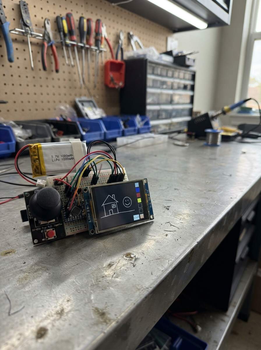
This portable sketchpad turns an ESP32 microcontroller into a drawing device with a joystick-controlled cursor and a vibrant ILI9341 color display. The dual-axis joystick moves the cursor across the screen, the built-in button switches between eight brush colors, and a dedicated clear button erases the canvas. A rechargeable LiPo battery powers the entire setup for untethered creative sessions.
This guide provides a complete parts list, wiring diagram showing all connections between the ESP32, joystick module, TFT display, buttons, and battery, step-by-step assembly instructions, and the Arduino firmware needed to run the sketchpad. Builders will learn how to interface analog joystick inputs, control a color display, and manage button debouncing for responsive drawing.
Wiring diagram

Gather all the parts
Assemble it in 6 steps
1. Place the XIAO and color screen
Put the XIAO ESP32-C3 and the 2.4-inch ILI9341 SPI color screen on a non-metal table. Use the pin labels printed on the screen; some screens call MOSI “DIN” or “SDI”, and SCK “CLK”.
- The project uses the landscape screen direction, with 320 pixels across and 240 pixels high.
- Do not use a screen that only accepts 5 V logic signals; the XIAO's pins use smaller 3.3 V signals.
2. Connect power to the color screen
Connect the ILI9341 VCC pin to XIAO 3V3 with a red wire, ILI9341 GND to XIAO GND with a black wire, and the screen LED or BL pin to XIAO 3V3 with a red wire. These wires power the screen, provide its return path, and keep its backlight on.
- VCC → 3V3 (power), GND → GND (ground), LED/BL → 3V3 (backlight power).
- Make sure VCC and GND are not swapped — swapped power can damage the screen.
3. Connect the screen data wires
Connect the ILI9341 MOSI, sometimes DIN or SDI, to XIAO D10/GPIO10; connect SCK, sometimes CLK, to XIAO D6/GPIO6; connect CS to XIAO D7/GPIO7; connect DC to XIAO D0/GPIO0; and connect RST or RESET to XIAO D1/GPIO1. These five wires carry the picture data and tell the screen when to listen.
- MOSI/DIN → GPIO10 (picture data), SCK/CLK → GPIO6 (clock), CS → GPIO7 (screen select), DC → GPIO0 (data/control), RST → GPIO1 (screen reset). Leave the TFT MISO/SDO pin unconnected.
- Do not connect the screen's touch pins, touch controller, or SD-card pins in this project. The screen must be the SPI ILI9341 version, not a parallel-pin version.
4. Wire the joystick
Connect joystick VCC to XIAO 3V3 and joystick GND to XIAO GND. Connect VRx to XIAO D0/GPIO2, VRy to XIAO D1/GPIO3, and SW to XIAO D2/GPIO4. The two VR wires report the stick direction and SW reports a joystick press.
- VCC → 3V3 (power), GND → GND (ground), VRx → GPIO2 (left/right signal), VRy → GPIO3 (up/down signal), SW → GPIO4 (press signal).
- Power the joystick from 3V3, not 5V — a 5 V signal can damage the XIAO input pins.
5. Add the clear button
Put the separate push button across the center gap of a breadboard. Connect one side of the button to XIAO D3/GPIO5 and the opposite side to XIAO GND. Pressing it wipes the whole drawing canvas.
- One button leg → GPIO5 (clear signal), opposite leg → GND (ground). A four-leg button has two joined legs on each side; use one leg from opposite sides of its center gap.
- If the button seems permanently pressed, rotate it a quarter turn so it crosses the breadboard’s center gap.
6. Connect the rechargeable battery
With the USB cable unplugged, connect the battery red positive lead to the XIAO BAT pad on its underside and the black negative lead to XIAO GND. This one-cell battery runs the project when it is away from USB power.
- Battery + → XIAO BAT pad (battery power), battery – → GND (ground). Charge the battery through the XIAO USB-C connector.
- Use only a single-cell 3.7 V LiPo battery. Do not connect it to 3V3 or 5V, and do not reverse its leads — either mistake can damage the board or battery.
Review all connections
1. Connections between "joystick_1" and "ESP32"
2. Connections between "clear_button_1" and "ESP32"
3. Connections between "battery_1" and "ESP32"
4. Connections between "ili9341_1" and "ESP32"
Deploy the firmware
#include <Arduino.h>
#include <SPI.h>
#include <Adafruit_GFX.h>
#include <Adafruit_ILI9341.h>


// Forward declarations
void drawStatus();
void drawCursor(int x, int y);
void eraseCursor(int x, int y);
void clearCanvas();
void moveCursorFromJoystick();
void readControls();

constexpr uint8_t TFT_MOSI_PIN = 10;
constexpr uint8_t TFT_MISO_PIN = 9;
constexpr uint8_t TFT_SCK_PIN = 6;
constexpr uint8_t TFT_CS_PIN = 7;
constexpr uint8_t TFT_DC_PIN = 0;
constexpr uint8_t TFT_RST_PIN = 1;
constexpr uint8_t TOUCH_CS_PIN = 8;
constexpr uint8_t JOYSTICK_X_PIN = 2;
constexpr uint8_t JOYSTICK_Y_PIN = 3;
constexpr uint8_t JOYSTICK_SWITCH_PIN = 4;
constexpr uint8_t CLEAR_BUTTON_PIN = 5;

constexpr int SCREEN_WIDTH = 320;
constexpr int SCREEN_HEIGHT = 240;
constexpr int STATUS_HEIGHT = 24;
constexpr int CANVAS_TOP = STATUS_HEIGHT;
constexpr int CURSOR_STEP = 3;
constexpr int CENTER_LOW = 1300;
constexpr int CENTER_HIGH = 2800;
constexpr unsigned long MOVE_INTERVAL_MS = 55;
constexpr unsigned long DEBOUNCE_MS = 35;
constexpr unsigned long HOLD_MS = 750;
constexpr uint8_t COLOR_COUNT = 8;

Adafruit_ILI9341 display(TFT_CS_PIN, TFT_DC_PIN, TFT_RST_PIN);

const uint16_t brushColors[COLOR_COUNT] = {
  ILI9341_WHITE, ILI9341_RED, ILI9341_GREEN, ILI9341_BLUE,
  ILI9341_YELLOW, ILI9341_CYAN, ILI9341_MAGENTA, ILI9341_ORANGE
};
const char *colorNames[COLOR_COUNT] = {
  "WHITE", "RED", "GREEN", "BLUE", "YELLOW", "CYAN", "MAGENTA", "ORANGE"
};

int cursorX = SCREEN_WIDTH / 2;
int cursorY = (CANVAS_TOP + SCREEN_HEIGHT) / 2;
uint8_t colorIndex = 0;
bool eraseMode = false;
bool joystickWasDown = false;
bool joystickHoldHandled = false;
bool clearWasDown = false;
unsigned long joystickDownMs = 0;
unsigned long lastMoveMs = 0;
unsigned long lastClearPressMs = 0;

void drawStatus() {
  display.fillRect(0, 0, SCREEN_WIDTH, STATUS_HEIGHT, ILI9341_DARKGREY);
  display.setTextSize(2);
  display.setTextColor(ILI9341_WHITE, ILI9341_DARKGREY);
  display.setCursor(5, 4);
  if (eraseMode) {
    display.print("ERASE");
  } else {
    display.print("DRAW ");
    display.setTextColor(brushColors[colorIndex], ILI9341_DARKGREY);
    display.print(colorNames[colorIndex]);
  }
  display.setTextColor(ILI9341_WHITE, ILI9341_DARKGREY);
  display.setCursor(174, 4);
  display.print("hold=mode");
}

void drawCursor(int x, int y) {
  uint16_t cursorColor = eraseMode ? ILI9341_WHITE : brushColors[colorIndex];
  display.drawRect(x - 3, y - 3, 7, 7, cursorColor);
}

void eraseCursor(int x, int y) {
  display.drawRect(x - 3, y - 3, 7, 7, ILI9341_BLACK);
}

void clearCanvas() {
  display.fillRect(0, CANVAS_TOP, SCREEN_WIDTH, SCREEN_HEIGHT - CANVAS_TOP, ILI9341_BLACK);
  drawStatus();
}

void moveCursorFromJoystick() {
  if (millis() - lastMoveMs < MOVE_INTERVAL_MS) return;

  int xReading = analogRead(JOYSTICK_X_PIN);
  int yReading = analogRead(JOYSTICK_Y_PIN);
  int dx = 0;
  int dy = 0;
  if (xReading < CENTER_LOW) dx = -CURSOR_STEP;
  else if (xReading > CENTER_HIGH) dx = CURSOR_STEP;
  if (yReading < CENTER_LOW) dy = -CURSOR_STEP;
  else if (yReading > CENTER_HIGH) dy = CURSOR_STEP;
  if (dx == 0 && dy == 0) return;

  eraseCursor(cursorX, cursorY);
  int oldX = cursorX;
  int oldY = cursorY;
  cursorX = constrain(cursorX + dx, 3, SCREEN_WIDTH - 4);
  cursorY = constrain(cursorY + dy, CANVAS_TOP + 3, SCREEN_HEIGHT - 4);
  uint16_t paintColor = eraseMode ? ILI9341_BLACK : brushColors[colorIndex];
  display.drawLine(oldX, oldY, cursorX, cursorY, paintColor);
  drawCursor(cursorX, cursorY);
  lastMoveMs = millis();
}

void readControls() {
  const unsigned long now = millis();
  const bool joystickDown = digitalRead(JOYSTICK_SWITCH_PIN) == LOW;
  const bool clearDown = digitalRead(CLEAR_BUTTON_PIN) == LOW;

  if (joystickDown && !joystickWasDown) {
    joystickDownMs = now;
    joystickHoldHandled = false;
  }
  if (joystickDown && !joystickHoldHandled && now - joystickDownMs >= HOLD_MS) {
    eraseCursor(cursorX, cursorY);
    eraseMode = !eraseMode;
    drawStatus();
    drawCursor(cursorX, cursorY);
    joystickHoldHandled = true;
  }
  if (!joystickDown && joystickWasDown && !joystickHoldHandled && now - joystickDownMs > DEBOUNCE_MS) {
    eraseCursor(cursorX, cursorY);
    colorIndex = (colorIndex + 1) % COLOR_COUNT;
    eraseMode = false;
    drawStatus();
    drawCursor(cursorX, cursorY);
  }

  if (clearDown && !clearWasDown && now - lastClearPressMs > DEBOUNCE_MS) {
    clearCanvas();
    drawCursor(cursorX, cursorY);
    lastClearPressMs = now;
  }
  joystickWasDown = joystickDown;
  clearWasDown = clearDown;
}

void setup() {
  pinMode(JOYSTICK_SWITCH_PIN, INPUT_PULLUP);
  pinMode(CLEAR_BUTTON_PIN, INPUT_PULLUP);
  pinMode(TOUCH_CS_PIN, OUTPUT);
  digitalWrite(TOUCH_CS_PIN, HIGH);
  analogReadResolution(12);

  SPI.begin(TFT_SCK_PIN, TFT_MISO_PIN, TFT_MOSI_PIN, TFT_CS_PIN);
  display.begin();
  display.setRotation(1);
  display.fillScreen(ILI9341_BLACK);
  drawStatus();
  drawCursor(cursorX, cursorY);
}

void loop() {
  readControls();
  moveCursorFromJoystick();
  delay(3);
}
Remix this project
Make it yours in one click
Open a full copy of this project in your own Schematik workspace — diagram, code, parts, and assembly steps included. Swap the sensor, add features, or redesign the whole thing with AI. The author's original stays untouched.