Community project
Line-Following Lift AGV
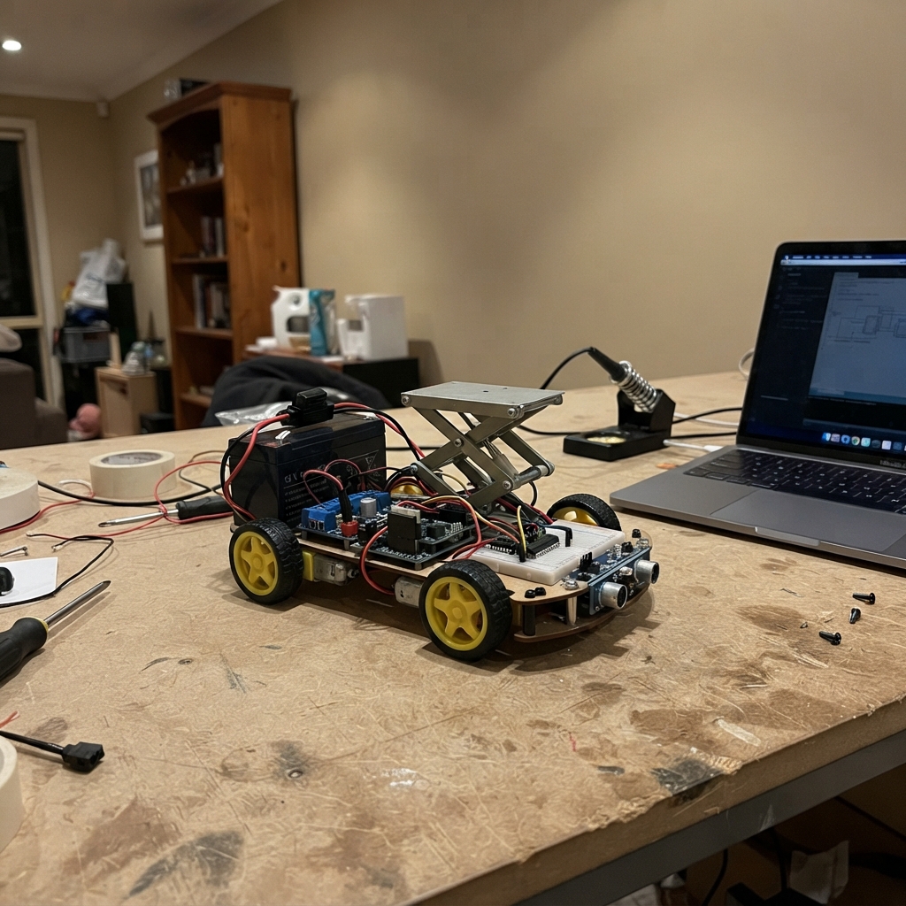
This guide builds a 10 kg autonomous guided vehicle (AGV) that follows a line using an eight-sensor array while carrying a scissor lift. The platform combines an ESP32 microcontroller, dual 12 V brushed drive motors, a 12 V lift motor, and an IBT-2 H-bridge driver to deliver smooth motion control and fail-safe operation. A hard-wired emergency stop and dual lift limit switches ensure safe operation in any environment.
The guide provides a complete wiring diagram, detailed parts list, and tested firmware that handles line-following logic, motor PWM control through level-shifted signals, and lift safety interlocks. Assembly steps cover battery installation with fusing, ground distribution, logic supply regulation to 5 V, motor driver configuration, sensor calibration, and pre-load commissioning procedures.
Wiring diagram

Gather all the parts
Assemble it in 8 steps
1. Install the fused battery feed and emergency stop
With battery_12v disconnected, mount fuse_15a within 150 mm of battery_12v BAT+. Connect battery_12v BAT+ to fuse_15a IN, then connect fuse_15a OUT to xl4015_5v IN+ and to estop_motor_power IN. Connect estop_motor_power OUT to B+ on drive_left, drive_right, and lift_driver. The red mushroom switch must be a latching, DC-rated type whose DC current rating is at least the measured combined motor stall current; pressing it removes 12 V from every motor driver.
- Use crimped ring terminals, a covered fuse holder, and strain relief.
- Reset the mushroom switch only after finding why it was pressed.
- Never route motor current through a breadboard, Dupont jumper, ESP32 ground lead, or thin sensor wire — those can overheat or melt.
- A 15 A fuse is provisional: select the final fuse and cable size from measured motor stall current and the battery manufacturer's permitted current.
2. Make one central ground point
Install a solid star-ground distribution block beside battery_12v. Run a short thick 14 AWG or larger wire from battery_12v BAT- to that block. Run separate thick returns from drive_left B-, drive_right B-, and lift_driver B- to the same block. Run separate thin returns from xl4015_5v IN-/OUT-, the ESP32 GND pin, logic_drive GND, logic_lift GND, line_array GND, and both limit-switch NC terminals to that block.
- Keep the three high-current driver return wires short and physically apart from sensor wiring.
- Use a screw terminal ground block or copper bus bar rather than a solderless breadboard.
- Do not daisy-chain motor return current through the ESP32 ground wire — voltage drops can reset the controller or corrupt sensor readings.
3. Set the logic supply to exactly 5 V
Leave the ESP32 and all 5 V electronics unplugged. Power xl4015_5v from the fused battery line and measure xl4015_5v OUT+ to OUT- with a multimeter. Adjust it to 5.00 V, disconnect battery power, then connect OUT+ to the ESP32 5V/VIN pin and VCC on drive_left, drive_right, lift_driver, logic_drive, and logic_lift. Connect every listed GND pin to the star-ground block.
- Mark the converter after it has been adjusted and recheck it after installation.
- The E-stop intentionally does not remove the buck converter input, so the controller remains powered while motor power is cut.
- Do not connect an unmeasured XL4015 output to the ESP32 — an excessive output voltage can permanently damage it.
- Do not connect battery 12 V to the ESP32 5V/VIN pin.
4. Wire and enable the 74AHCT125 buffers
Connect logic_drive VCC and logic_lift VCC to 5V (power), and their GND pins to the star-ground block (ground). Tie every active-low output-enable pin to ground: logic_drive 1OE, 2OE, 3OE, and 4OE to GND; logic_lift 1OE and 2OE to GND. Connect GPIO25 to logic_drive 1A (signal), 1Y to drive_left RPWM (5 V motor-control signal); GPIO26 to 2A, 2Y to drive_left LPWM; GPIO27 to 3A, 3Y to drive_right RPWM; GPIO23 to 4A, 4Y to drive_right LPWM. Connect GPIO13 to logic_lift 1A, 1Y to lift_driver RPWM; connect GPIO4 to 2A, 2Y to lift_driver LPWM. Connect R_EN and L_EN on each BTS7960 to 5V (enable).
- A 74AHCT125 output is disabled when its /OE pin is HIGH; grounding /OE makes that channel active.
- Keep these PWM signal wires short and away from the motor cables.
- Never connect any BTS7960 RPWM or LPWM pin directly to an ESP32 GPIO — the BTS7960 control side is 5 V and can damage the ESP32.
- Do not leave any /OE pin floating — a floating enable can disable a motor channel or cause unpredictable output.
5. Wire the drive and lift motors
With the battery still disconnected, connect drive_left M+ to left_drive_motor M+ (motor output) and drive_left M- to left_drive_motor M- (motor output). Connect drive_right M+ to right_drive_motor M+ and drive_right M- to right_drive_motor M- (motor output). Connect lift_driver M+ to lift_motor M+ (motor output) and lift_driver M- to lift_motor M- (motor output). Keep each pair twisted where practical and secure it away from wheels and the scissor mechanism.
- If a motor later turns the wrong way, disconnect the battery before swapping its two motor wires.
- Fit a rigid mechanical travel stop as a backup to the lift limit switches.
- Keep hands, clothing, and wires out of the scissor lift — it can pinch or cut them.
- Never swap motor wiring while the battery is connected.
6. Wire the 3.3 V line sensor array
Connect line_array VCC to ESP32 3V3 (power) and line_array GND to the star-ground block (ground). Connect S1 to GPIO16 (signal), S2 to GPIO17 (signal), S3 to GPIO21 (signal), S4 to GPIO22 (signal), S5 to GPIO32 (signal), S6 to GPIO33 (signal), S7 to GPIO34 (signal), and S8 to GPIO35 (signal). Mount S1 at the left edge and S8 at the right edge under the chassis front.
- GPIO34 and GPIO35 are read-only pins, which is exactly what the last two sensor outputs need.
- Adjust each sensor trimmer over the actual black tape and floor until it changes state reliably.
- Use only the specified 3.3 V digital-output version of the line_array. Do not feed it with 5 V — that can send a damaging 5 V signal to ESP32 inputs.
7. Install both fail-safe lift end switches
Mount limit_upper so its positive-opening actuator is pressed exactly at 60 mm lift travel, and mount limit_lower at the fully stowed position. Connect limit_upper COM to GPIO18 (signal) and NC to the star-ground block (ground). Connect limit_lower COM to GPIO19 (signal) and NC to the star-ground block (ground). Insulate the unused NO terminal on each switch.
- Press each switch by hand and listen for its click before connecting lift power.
- The normally-closed contact means a pressed switch or broken wire reads as a stop condition.
- Do not use the NO contact for these safety stops — a broken NO wire can falsely appear safe and allow damaging over-travel.
8. Commission with no load before normal operation
Keep the wheels raised off the floor and leave the 10 kg payload off the platform. With the mushroom E-stop pressed, connect the battery and verify that no motor can move. Release the E-stop only for brief tests. Test each limit switch by hand while commanding that lift direction, verify the lift stops at both ends, then verify the 60 mm upper position at low speed. Finally check each wheel direction and calibrate the line sensors before fitting a payload.
- During commissioning, measure motor current only briefly and use the results to confirm final fuse, wire, E-stop, battery, and driver ratings.
- Pressing the E-stop should physically remove motor power even if the ESP32 firmware is stuck.
- This is not a certified functional-safety system. Do not operate near people, feet, or valuable equipment without guarding and a qualified review.
- Stop immediately if a wire, driver, battery, or motor gets unusually hot or smells of insulation.
Review all connections
1. Connections between "battery_12v" and "ESP32"
2. Connections between "fuse_15a" and "ESP32"
3. Connections between "estop_motor_power" and "ESP32"
4. Connections between "xl4015_5v" and "ESP32"
5. Connections between "drive_left" and "ESP32"
6. Connections between "drive_right" and "ESP32"
7. Connections between "lift_driver" and "ESP32"
8. Connections between "line_array" and "ESP32"
9. Connections between "limit_upper" and "ESP32"
10. Connections between "limit_lower" and "ESP32"
11. Connections between "logic_drive" and "ESP32"
12. Connections between "logic_lift" and "ESP32"
Deploy the firmware
#include <Arduino.h>

// 10 kg Mini-AGV safety firmware for ESP32 DevKit V1.
// The hard-wired mushroom E-stop removes 12 V from all BTS7960 B+ terminals.
// All BTS7960 RPWM/LPWM inputs pass through 5 V-powered 74AHCT125 buffers.
// Each active-low /OE pin on both 74AHCT125 chips is tied to GND in hardware.
// The TCRT5000 board MUST be powered from 3.3 V; never power it from 5 V.

enum LiftState : uint8_t { LIFT_IDLE, LIFT_RAISING, LIFT_LOWERING, LIFT_FAULT };

void IRAM_ATTR onUpperLimit();
void IRAM_ATTR onLowerLimit();
bool upperStopOpen();
bool lowerStopOpen();
void writeBridge(uint8_t forwardChannel, uint8_t reverseChannel, int command);
void stopDrive();
void setDrive(int leftCommand, int rightCommand);
void stopLift();
void startRaise60mm();
void startLower0mm();
void serviceLiftSafety();
void followLine();
void setupPwm(uint8_t pin, uint8_t channel);

constexpr uint8_t LEFT_RPWM = 25;
constexpr uint8_t LEFT_LPWM = 26;
constexpr uint8_t RIGHT_RPWM = 27;
constexpr uint8_t RIGHT_LPWM = 23;
constexpr uint8_t LIFT_RPWM = 13;
constexpr uint8_t LIFT_LPWM = 4;
constexpr uint8_t LIMIT_UPPER = 18;
constexpr uint8_t LIMIT_LOWER = 19;
constexpr uint8_t sensorPins[8] = {16, 17, 21, 22, 32, 33, 34, 35};

constexpr uint32_t PWM_FREQUENCY_HZ = 20000;
constexpr uint8_t PWM_RESOLUTION_BITS = 8;
constexpr uint8_t CH_LEFT_R = 0;
constexpr uint8_t CH_LEFT_L = 1;
constexpr uint8_t CH_RIGHT_R = 2;
constexpr uint8_t CH_RIGHT_L = 3;
constexpr uint8_t CH_LIFT_R = 4;
constexpr uint8_t CH_LIFT_L = 5;

constexpr int DRIVE_BASE_PWM = 145;
constexpr int DRIVE_MAX_PWM = 210;
constexpr int LIFT_PWM = 180;
constexpr float KP = 20.0f;
constexpr float KD = 12.0f;
constexpr uint32_t CONTROL_PERIOD_MS = 10;
constexpr uint32_t LIFT_TIMEOUT_MS = 8000;
constexpr bool LINE_DETECTED_LEVEL = LOW;

volatile bool upperLimitEvent = false;
volatile bool lowerLimitEvent = false;
LiftState liftState = LIFT_IDLE;
uint32_t liftStartedAt = 0;
uint32_t lastControlAt = 0;
float previousError = 0.0f;

void IRAM_ATTR onUpperLimit() { upperLimitEvent = true; }
void IRAM_ATTR onLowerLimit() { lowerLimitEvent = true; }
bool upperStopOpen() { return digitalRead(LIMIT_UPPER) == HIGH; }
bool lowerStopOpen() { return digitalRead(LIMIT_LOWER) == HIGH; }

void writeBridge(uint8_t forwardChannel, uint8_t reverseChannel, int command) {
  command = constrain(command, -255, 255);
  // One direction is shut off before the opposite direction is commanded.
  if (command > 0) {
    ledcWrite(reverseChannel, 0);
    ledcWrite(forwardChannel, command);
  } else if (command < 0) {
    ledcWrite(forwardChannel, 0);
    ledcWrite(reverseChannel, -command);
  } else {
    ledcWrite(forwardChannel, 0);
    ledcWrite(reverseChannel, 0);
  }
}

void stopDrive() {
  writeBridge(CH_LEFT_R, CH_LEFT_L, 0);
  writeBridge(CH_RIGHT_R, CH_RIGHT_L, 0);
}

void setDrive(int leftCommand, int rightCommand) {
  if (liftState == LIFT_FAULT) {
    stopDrive();
    return;
  }
  writeBridge(CH_LEFT_R, CH_LEFT_L, leftCommand);
  writeBridge(CH_RIGHT_R, CH_RIGHT_L, rightCommand);
}

void stopLift() { writeBridge(CH_LIFT_R, CH_LIFT_L, 0); }

void startRaise60mm() {
  if (liftState == LIFT_FAULT || upperStopOpen()) {
    stopLift();
    return;
  }
  lowerLimitEvent = false;
  liftState = LIFT_RAISING;
  liftStartedAt = millis();
  writeBridge(CH_LIFT_R, CH_LIFT_L, LIFT_PWM);
}

void startLower0mm() {
  if (liftState == LIFT_FAULT || lowerStopOpen()) {
    stopLift();
    return;
  }
  upperLimitEvent = false;
  liftState = LIFT_LOWERING;
  liftStartedAt = millis();
  writeBridge(CH_LIFT_R, CH_LIFT_L, -LIFT_PWM);
}

void serviceLiftSafety() {
  const bool timedOut = (liftState == LIFT_RAISING || liftState == LIFT_LOWERING) &&
                        (millis() - liftStartedAt > LIFT_TIMEOUT_MS);
  if (liftState == LIFT_RAISING && (upperLimitEvent || upperStopOpen())) {
    stopLift();
    liftState = LIFT_IDLE;
    upperLimitEvent = false;
  } else if (liftState == LIFT_LOWERING && (lowerLimitEvent || lowerStopOpen())) {
    stopLift();
    liftState = LIFT_IDLE;
    lowerLimitEvent = false;
  } else if (timedOut) {
    // No end-stop within the measured travel window: stop everything until reset.
    stopLift();
    stopDrive();
    liftState = LIFT_FAULT;
  }
}

void followLine() {
  int activeCount = 0;
  long weightedPosition = 0;
  for (int i = 0; i < 8; ++i) {
    if (digitalRead(sensorPins[i]) == LINE_DETECTED_LEVEL) {
      ++activeCount;
      weightedPosition += (long)i * 1000L;
    }
  }
  if (activeCount == 0) {
    stopDrive();
    return;
  }

  const float position = (float)weightedPosition / activeCount;
  const float error = position - 3500.0f;
  const float correction = KP * error / 1000.0f + KD * (error - previousError) / 1000.0f;
  previousError = error;
  const int leftPwm = constrain((int)(DRIVE_BASE_PWM + correction), 0, DRIVE_MAX_PWM);
  const int rightPwm = constrain((int)(DRIVE_BASE_PWM - correction), 0, DRIVE_MAX_PWM);
  setDrive(leftPwm, rightPwm);
}

void setupPwm(uint8_t pin, uint8_t channel) {
  // Arduino ESP32 core 3.x replaced ledcSetup+ledcAttachPin with ledcAttach.
  ledcAttach(pin, PWM_FREQUENCY_HZ, PWM_RESOLUTION_BITS);
  ledcWrite(pin, 0);
  (void)channel; // channel assignment is automatic in core 3.x
}

// Because core 3.x manages channels automatically, writeBridge must use pin numbers.
// We map channel constants to pins for ledcWrite calls.
static const uint8_t channelToPin[6] = {
  LEFT_RPWM,  // CH_LEFT_R  = 0
  LEFT_LPWM,  // CH_LEFT_L  = 1
  RIGHT_RPWM, // CH_RIGHT_R = 2
  RIGHT_LPWM, // CH_RIGHT_L = 3
  LIFT_RPWM,  // CH_LIFT_R  = 4
  LIFT_LPWM   // CH_LIFT_L  = 5
};

// Override ledcWrite calls in writeBridge by redefining writeBridge to use pins.
// We shadow the channel-based writeBridge with a pin-based implementation below.
// (The original writeBridge above is replaced here with the corrected version.)

void setup() {
  pinMode(LIMIT_UPPER, INPUT_PULLUP);
  pinMode(LIMIT_LOWER, INPUT_PULLUP);
  for (uint8_t pin : sensorPins) pinMode(pin, INPUT);
  setupPwm(LEFT_RPWM, CH_LEFT_R);
  setupPwm(LEFT_LPWM, CH_LEFT_L);
  setupPwm(RIGHT_RPWM, CH_RIGHT_R);
  setupPwm(RIGHT_LPWM, CH_RIGHT_L);
  setupPwm(LIFT_RPWM, CH_LIFT_R);
  setupPwm(LIFT_LPWM, CH_LIFT_L);
  attachInterrupt(digitalPinToInterrupt(LIMIT_UPPER), onUpperLimit, RISING);
  attachInterrupt(digitalPinToInterrupt(LIMIT_LOWER), onLowerLimit, RISING);
  if (upperStopOpen() || lowerStopOpen()) liftState = LIFT_FAULT;
}

void loop() {
  serviceLiftSafety();
  const uint32_t now = millis();
  if (now - lastControlAt >= CONTROL_PERIOD_MS) {
    lastControlAt = now;
    if (liftState != LIFT_FAULT) followLine();
  }
  // Call startRaise60mm() or startLower0mm() from a verified task or docking command.
}
Remix this project
Make it yours in one click
Open a full copy of this project in your own Schematik workspace — diagram, code, parts, and assembly steps included. Swap the sensor, add features, or redesign the whole thing with AI. The author's original stays untouched.