Community project
Oficina: Estado Y Temporizador
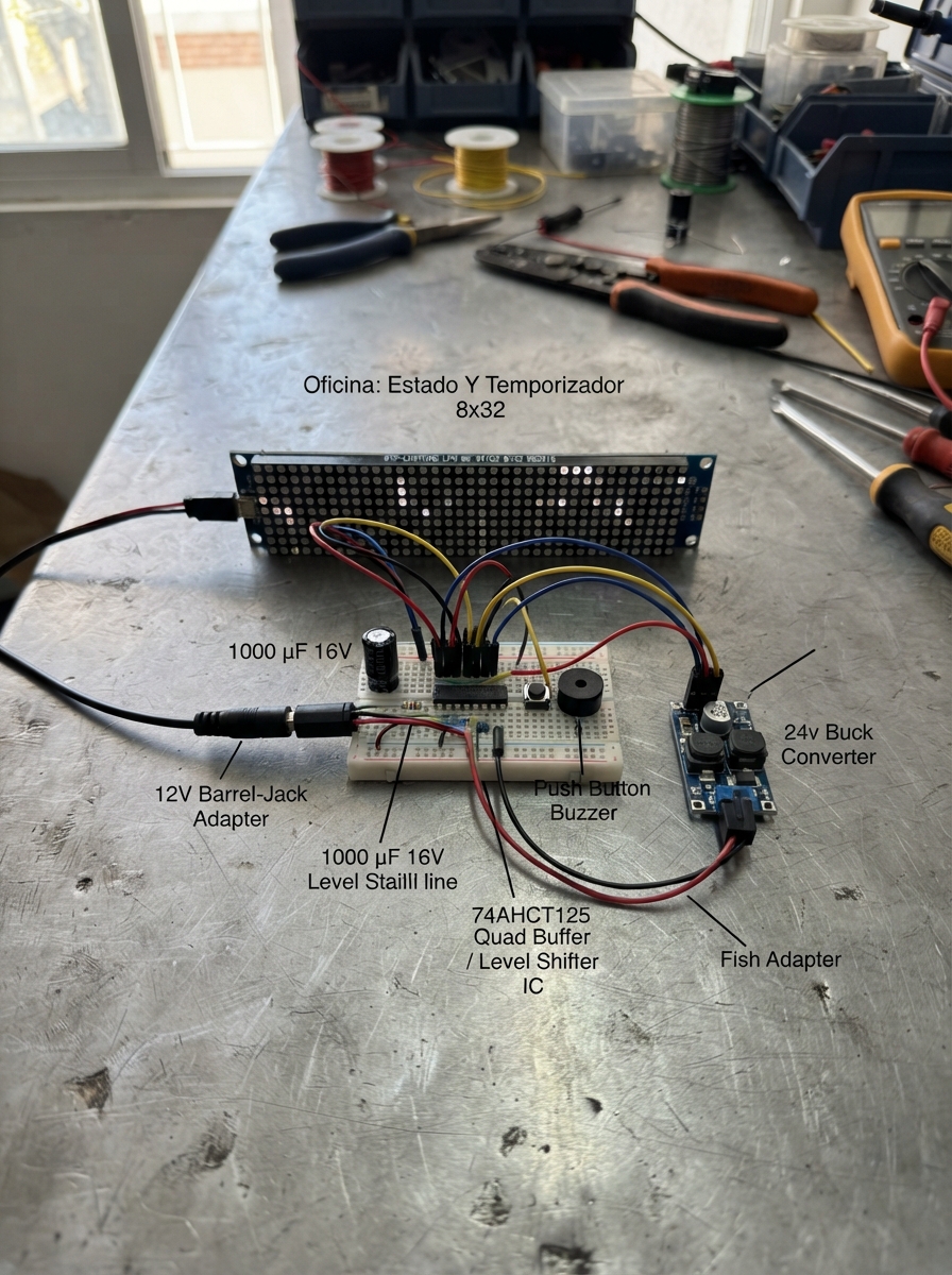
Build an office status display and timer using an ESP32 microcontroller and a 32×8 RGB LED matrix. This project combines Wi-Fi connectivity with physical controls to show availability status (online, busy, away, or alarm) with color-coded indicators and scrolling text messages. The guide includes a complete wiring diagram, parts list, firmware code, and step-by-step assembly instructions for powering the matrix, configuring the voltage regulators, and integrating the push button and buzzer for local control.
The system runs a web interface for remote status updates while supporting manual control via the physical button. The LED matrix displays your current status with animated text, and the buzzer provides audio feedback. Perfect for home offices, maker spaces, or collaborative environments where team members need to see at a glance whether you are available.
Wiring diagram

Gather all the parts
Assemble it in 6 steps
1. Prepara la fuente de 12 V
Con la fuente desenchufada, conecta su cable positivo de 12 V al terminal 12V del panel y a VIN+ del convertidor LM2596. Conecta su cable negativo a GND del panel y a VIN- del convertidor. Coloca el condensador cerca del panel: su pata marcada con una franja va al negativo y la otra pata al positivo de 12 V.
- El panel tiene muchas luces y necesita una fuente de 12 V de al menos 3 A, aunque el texto use poco brillo.
- Usa cables algo más gruesos para los dos cables que llevan 12 V al panel.
- No conectes los 12 V a ningún pin del XIAO; hacerlo puede dañarlo inmediatamente.
- No inviertas el condensador: si se conecta al revés puede calentarse o romperse.
2. Ajusta el convertidor a 5 V
Antes de conectar el XIAO, enchufa la fuente y usa un multímetro en VOUT+ y VOUT- del LM2596. Gira con cuidado el pequeño tornillo del convertidor hasta medir exactamente 5,0 V. Después desenchufa de nuevo la fuente.
- Este ajuste se hace una sola vez y protege la placa.
- Marca los bornes de salida del convertidor como 5V y GND cuando termines.
- No conectes la salida del convertidor al XIAO hasta haber comprobado que es 5 V; un ajuste demasiado alto puede dañar la placa.
3. Da 5 V al XIAO y al adaptador de señal
Conecta VOUT+ del LM2596 al pin 5V/VBUS del XIAO y también a VCC del 74AHCT125. Conecta VOUT- a GND del XIAO, GND del 74AHCT125 y al negativo común del panel. Une 1OE del 74AHCT125 a GND para que su salida quede siempre encendida.
- Todas las piezas deben compartir el mismo GND; sin esa conexión común el panel no entenderá los datos.
- Si usas un chip suelto en vez de un módulo, mira la muesca del encapsulado para localizar correctamente sus patas.
- No alimentes VCC del 74AHCT125 con 12 V; este chip necesita 5 V.
- Asegúrate de que la tierra del panel también está unida a la tierra del XIAO; omitirla puede producir texto errático.
4. Conecta la señal del panel
Conecta el pin D9/MISO del XIAO, que corresponde a GPIO20, a 1A del 74AHCT125. Conecta 1Y del 74AHCT125 a un extremo de la resistencia de 470 Ω. Conecta el otro extremo de la resistencia a DIN del panel, usando el extremo del panel marcado como entrada de datos.
- Sigue las flechas impresas en el panel: DIN es el extremo por el que entra la señal.
- La resistencia puede colocarse en cualquiera de los dos sentidos.
- Conectar la señal a DOUT en vez de DIN hará que el panel no muestre el mensaje.
- No omitas la resistencia de 470 Ω: ayuda a evitar errores de señal y protege la primera luz del panel.
5. Monta el botón y la alarma
Conecta una pata del pulsador a GPIO2 del XIAO, marcado D2, y la pata opuesta a GND. Conecta SIGNAL del zumbador activo a GPIO21 del XIAO, marcado D3, y su GND a GND común.
- El programa usa la resistencia interna del XIAO, por eso el botón solo necesita dos cables.
- En un pulsador de cuatro patas, usa dos patas que estén en lados opuestos, no dos del mismo lado.
- Si el zumbador tiene marcas + y -, conecta su terminal negativo a GND; invertirlo puede impedir que suene.
6. Enciende y usa el cartel
Revisa una última vez que el panel recibe 12 V y que el XIAO recibe solo 5 V. Enchufa la fuente y conecta el XIAO por USB. Un toque del botón cambia ONLINE, AUSENTE y OCUPADO de 15 minutos. Mantén el botón pulsado para elegir 15, 30, 45 o 60 minutos; da toques para cambiar el tiempo y mantenlo pulsado otra vez para iniciar la cuenta. Para usar el teléfono, conéctate a la red Oficina-Estado con la contraseña oficina2026 y abre 192.168.4.1.
- Cuando el tiempo termina, el texto avisa y el zumbador hace pulsos; un toque del botón detiene el aviso y vuelve a ONLINE.
- El brillo está limitado para una oficina interior y para reducir consumo y calor.
- Desenchufa la fuente antes de mover cables; un corto entre los 12 V y GND puede calentar cables o dañar piezas.
Review all connections
1. Connections between "power_supply_12v" and "ESP32"
2. Connections between "led_matrix" and "ESP32"
3. Connections between "buck_5v" and "ESP32"
4. Connections between "level_shifter" and "ESP32"
5. Connections between "data_resistor" and "ESP32"
6. Connections between "alarm_buzzer" and "ESP32"
7. Connections between "mode_button" and "ESP32"
8. Connections between "supply_capacitor" and "ESP32"
Deploy the firmware
#include <Arduino.h>
// The browser simulator has no usable WebServer implementation when a library facade is active.
// Keep the office Wi-Fi control page in every physical ESP32 build.
#if !defined(__wasm__)
#include <WiFi.h>
#include <WebServer.h>
#endif
#include <Adafruit_GFX.h>
#include <Adafruit_NeoPixel.h>
#include <Adafruit_NeoMatrix.h>

// The browser simulator's NeoMatrix facade does not publish these layout flags.
// Real Adafruit_NeoMatrix builds already define them, so this changes nothing on hardware.
#ifndef NEO_MATRIX_TOP
#define NEO_MATRIX_TOP 0x00
#endif
#ifndef NEO_MATRIX_LEFT
#define NEO_MATRIX_LEFT 0x00
#endif
#ifndef NEO_MATRIX_ROWS
#define NEO_MATRIX_ROWS 0x00
#endif
#ifndef NEO_MATRIX_ZIGZAG
#define NEO_MATRIX_ZIGZAG 0x00
#endif

enum Status { ONLINE, BUSY, AWAY, ALARM };


// Forward declarations
uint16_t colorFor(Status value);
String statusText();
void setStatus(Status next);
void startBusy(uint8_t minutes);
void drawMessage(bool moveText);
void servePage();
void handleSet();
void handleButton();

constexpr uint8_t MATRIX_PIN = 20;
constexpr uint8_t BUZZER_PIN = 21;
constexpr uint8_t BUTTON_PIN = 2;
constexpr uint8_t MATRIX_WIDTH = 32;
constexpr uint8_t MATRIX_HEIGHT = 8;
constexpr uint8_t MATRIX_BRIGHTNESS = 32;  // Interior: limita corriente y calor.
constexpr unsigned long FRAME_MS = 50;
constexpr unsigned long LONG_PRESS_MS = 1200;

Adafruit_NeoMatrix matrix(MATRIX_WIDTH, MATRIX_HEIGHT, MATRIX_PIN,
  NEO_MATRIX_TOP + NEO_MATRIX_LEFT + NEO_MATRIX_ROWS + NEO_MATRIX_ZIGZAG,
  NEO_GRB + NEO_KHZ800);
#if !defined(__wasm__)
WebServer server(80);
#endif

Status status = ONLINE;

unsigned long busyEndsAt = 0;
unsigned long lastFrameAt = 0;
unsigned long buttonDownAt = 0;
bool buttonWasDown = false;
bool selectingTime = false;
uint8_t selectedMinutes = 15;
int16_t textX = MATRIX_WIDTH;
String lastDrawnText;
uint16_t lastDrawnColor = 0;

uint16_t colorFor(Status value) {
  if (value == ONLINE) return matrix.Color(0, 180, 0);
  if (value == BUSY) return matrix.Color(220, 0, 0);
  if (value == AWAY) return matrix.Color(180, 105, 0);
  return matrix.Color(230, 0, 0);
}

String statusText() {
  if (selectingTime) return "ELIGE " + String(selectedMinutes) + " MIN";
  if (status == ONLINE) return "ONLINE";
  if (status == AWAY) return "AUSENTE";
  if (status == ALARM) return "TIEMPO TERMINADO";
  unsigned long remaining = (busyEndsAt > millis()) ? (busyEndsAt - millis()) : 0;
  unsigned long seconds = remaining / 1000UL;
  char buffer[32];
  snprintf(buffer, sizeof(buffer), "OCUPADO %02lu:%02lu", seconds / 60UL, seconds % 60UL);
  return String(buffer);
}

void setStatus(Status next) {
  status = next;
  selectingTime = false;
  if (next != BUSY) busyEndsAt = 0;
  digitalWrite(BUZZER_PIN, LOW);
  textX = MATRIX_WIDTH;
  lastDrawnText = "";
}

void startBusy(uint8_t minutes) {
  selectedMinutes = minutes;
  busyEndsAt = millis() + (unsigned long)minutes * 60000UL;
  status = BUSY;
  selectingTime = false;
  digitalWrite(BUZZER_PIN, LOW);
  textX = MATRIX_WIDTH;
  lastDrawnText = "";
}

void drawMessage(bool moveText) {
  String message = statusText();
  uint16_t color = colorFor(status);
  if (selectingTime) color = matrix.Color(0, 80, 200);

  if (message != lastDrawnText || color != lastDrawnColor) {
    textX = MATRIX_WIDTH;
    lastDrawnText = message;
    lastDrawnColor = color;
  }
  if (moveText) textX--;
  int16_t messageWidth = message.length() * 6;
  if (textX < -messageWidth) textX = MATRIX_WIDTH;

  matrix.fillScreen(0);
  matrix.setTextWrap(false);
  matrix.setTextColor(color);
  matrix.setCursor(textX, 1);
  matrix.print(message);
  matrix.show();
}

#if !defined(__wasm__)
void servePage() {
  unsigned long remaining = (status == BUSY && busyEndsAt > millis()) ? (busyEndsAt - millis()) / 1000UL : 0;
  String state = status == ONLINE ? "ONLINE" : status == BUSY ? "OCUPADO" : status == AWAY ? "AUSENTE" : "ALARMA";
  String page = "<!doctype html><html><meta name='viewport' content='width=device-width,initial-scale=1'>"
                "<style>body{font-family:sans-serif;max-width:420px;margin:30px auto;padding:0 16px}button,input{font-size:18px;padding:12px;margin:5px}button{border:0;border-radius:8px;color:white;background:#1565c0}.online{background:#168a24}.busy{background:#c62828}.away{background:#b26a00}</style>"
                "<h1>Cartel de oficina</h1><p>Estado actual: <b>" + state + "</b></p>";
  if (status == BUSY) {
    page += "<p>Quedan ";
    page += String(remaining / 60);
    page += " min ";
    page += String(remaining % 60);
    page += " s.</p>";
  }
  page += "<p><a href='/set?mode=online'><button class='online'>ONLINE</button></a>"
          "<a href='/set?mode=away'><button class='away'>AUSENTE</button></a></p>"
          "<form action='/set'><input type='hidden' name='mode' value='busy'><label>OCUPADO: <input name='minutes' type='number' min='1' max='240' value='15'> minutos</label><button class='busy' type='submit'>Iniciar</button></form>"
          "<p>Red Wi-Fi: <b>Oficina-Estado</b><br>Abre <b>192.168.4.1</b> después de conectarte.</p></html>";
  server.send(200, "text/html; charset=utf-8", page);
}

void handleSet() {
  String mode = server.arg("mode");
  if (mode == "online") setStatus(ONLINE);
  else if (mode == "away") setStatus(AWAY);
  else if (mode == "busy") {
    int minutes = constrain(server.arg("minutes").toInt(), 1, 240);
    if (minutes == 0) minutes = 15;
    startBusy((uint8_t)minutes);
  }
  server.sendHeader("Location", "/");
  server.send(303);
}
#endif

void handleButton() {
  bool down = digitalRead(BUTTON_PIN) == LOW;
  if (down && !buttonWasDown) {
    buttonDownAt = millis();
    buttonWasDown = true;
  }
  if (!down && buttonWasDown) {
    unsigned long held = millis() - buttonDownAt;
    buttonWasDown = false;
    if (status == ALARM) {
      setStatus(ONLINE);
    } else if (held >= LONG_PRESS_MS) {
      if (selectingTime) startBusy(selectedMinutes);
      else {
        selectingTime = true;
        selectedMinutes = 15;
        textX = MATRIX_WIDTH;
        lastDrawnText = "";
      }
    } else if (selectingTime) {
      selectedMinutes += 15;
      if (selectedMinutes > 60) selectedMinutes = 15;
      textX = MATRIX_WIDTH;
      lastDrawnText = "";
    } else if (status == ONLINE) {
      setStatus(AWAY);
    } else if (status == AWAY) {
      startBusy(15);
    } else {
      setStatus(ONLINE);
    }
  }
}

void setup() {
  pinMode(BUZZER_PIN, OUTPUT);
  digitalWrite(BUZZER_PIN, LOW);
  pinMode(BUTTON_PIN, INPUT_PULLUP);
  matrix.begin();
  matrix.setBrightness(MATRIX_BRIGHTNESS);
  matrix.setTextSize(1);
  matrix.fillScreen(0);
  matrix.show();

#if !defined(__wasm__)
  WiFi.mode(WIFI_AP);
  WiFi.softAP("Oficina-Estado", "oficina2026");
  server.on("/", HTTP_GET, servePage);
  server.on("/set", HTTP_GET, handleSet);
  server.begin();
#endif
}

void loop() {
#if !defined(__wasm__)
  server.handleClient();
#endif
  handleButton();

  if (status == BUSY && millis() >= busyEndsAt) {
    status = ALARM;
    busyEndsAt = 0;
    textX = MATRIX_WIDTH;
    lastDrawnText = "";
  }
  digitalWrite(BUZZER_PIN, status == ALARM ? ((millis() / 300UL) % 2) : LOW);

  if (millis() - lastFrameAt >= FRAME_MS) {
    lastFrameAt = millis();
    drawMessage(true);
  }
}
Remix this project
Make it yours in one click
Open a full copy of this project in your own Schematik workspace — diagram, code, parts, and assembly steps included. Swap the sensor, add features, or redesign the whole thing with AI. The author's original stays untouched.