Community project
Onboard LED Controller
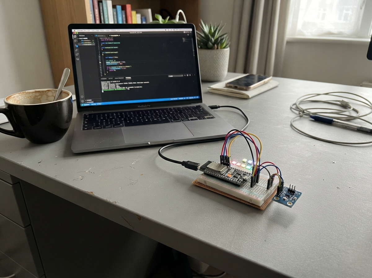
This project uses an ESP32 microcontroller and an SHT30 temperature and humidity sensor to monitor environmental conditions and control an onboard LED. The LED turns on when the temperature exceeds 28°C, providing a simple visual indicator of thermal conditions. The sensor readings are also logged to the serial monitor for real-time monitoring.
This guide includes a complete wiring diagram showing how to connect the SHT30 sensor to the ESP32 via I2C, a full parts list, and ready-to-use firmware. Assembly takes just a few minutes: connect the sensor to GPIO pins 21 and 22, verify the onboard LED on GPIO2, and power the board via USB.
Wiring diagram

Gather all the parts
Assemble it in 3 steps
1. 连接温湿度传感器
先不要给开发板通电。用 Gravity 4 芯线把 SHT31 传感器接到 DFR0654 的 I²C 接口;如果改用散装杜邦线,则把传感器 VCC 接到板子的 3V3 针、GND 接到 GND 针、SDA 接到 GPIO21、SCL 接到 GPIO22。
- Gravity 线的插头有防呆缺口,插入时不要硬掰;确认插头完全插到底。
- 若使用杜邦线,请按照传感器丝印 VCC、GND、SDA、SCL 逐一核对。
- 不要把传感器的 VCC 接到 5V;虽然模块可能支持 5V 供电,但使用 3.3V 能确保数据线电压不会损坏 ESP32。
- 不要把 VCC 和 GND 接反;接反可能损坏传感器。
2. 确认 GPIO5 的板载灯
不需要外接 LED 或电阻。程序使用 DFR0654 板子上由 GPIO5 控制的板载灯;当测得温度严格高于 25°C 时它会亮,25°C 或更低时它会熄灭。
- 传感器不要紧贴发热的电脑、USB 转换器或手掌,否则读数会暂时偏高。
- 不要再把外部元件接到 GPIO5;它已经用于控制板载灯。
3. 接通 USB 电源
再次检查四根传感器线无误后,用 USB 数据线把 DFR0654 接到电脑,为开发板供电并准备烧录程序。
- 刚接通电源后等待几秒,让传感器读数稳定。
- 如果传感器或导线异常发热,立刻拔掉 USB 线并检查 VCC 和 GND 是否接反。
Review all connections
1. Connections between "sht31_1" and "ESP32"
Deploy the firmware
#include <Arduino.h>
#include <Wire.h>
#include <Adafruit_SHT31.h>

constexpr int SHT31_SDA_PIN = 21;
constexpr int SHT31_SCL_PIN = 22;
constexpr int STATUS_LED_PIN = 2;
constexpr float TEMPERATURE_LIMIT_C = 28.0f;
constexpr unsigned long READ_INTERVAL_MS = 1000;

Adafruit_SHT31 sht31 = Adafruit_SHT31();
bool sensorReady = false;
unsigned long lastReadMs = 0;

void setup() {
  Serial.begin(115200);
  pinMode(STATUS_LED_PIN, OUTPUT);
  digitalWrite(STATUS_LED_PIN, LOW);

  Wire.begin(SHT31_SDA_PIN, SHT31_SCL_PIN);
  sensorReady = sht31.begin(0x44);
  if (!sensorReady) {
    Serial.println("SHT31 not found; check VCC, GND, SDA, and SCL.");
  }
}

void loop() {
  const unsigned long now = millis();
  if (now - lastReadMs < READ_INTERVAL_MS) {
    return;
  }
  lastReadMs = now;

  if (!sensorReady) {
    sensorReady = sht31.begin(0x44);
    digitalWrite(STATUS_LED_PIN, LOW);
    return;
  }

  const float temperatureC = sht31.readTemperature();
  const float humidity = sht31.readHumidity();

  if (isnan(temperatureC) || isnan(humidity)) {
    digitalWrite(STATUS_LED_PIN, LOW);
    Serial.println("SHT31 reading failed; LED turned off.");
    return;
  }

  digitalWrite(STATUS_LED_PIN, temperatureC > TEMPERATURE_LIMIT_C ? HIGH : LOW);
  Serial.print("Temperature: ");
  Serial.print(temperatureC, 1);
  Serial.print(" C, humidity: ");
  Serial.print(humidity, 1);
  Serial.print(" %; GPIO2 / D9 LED: ");
  Serial.println(temperatureC > TEMPERATURE_LIMIT_C ? "ON" : "OFF");
}
Remix this project
Make it yours in one click
Open a full copy of this project in your own Schematik workspace — diagram, code, parts, and assembly steps included. Swap the sensor, add features, or redesign the whole thing with AI. The author's original stays untouched.