Community project
Phone-Controlled Mini Drone
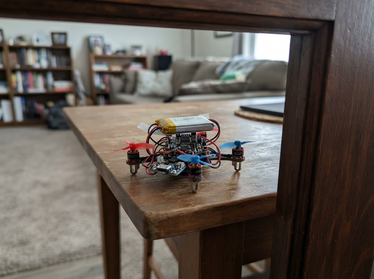
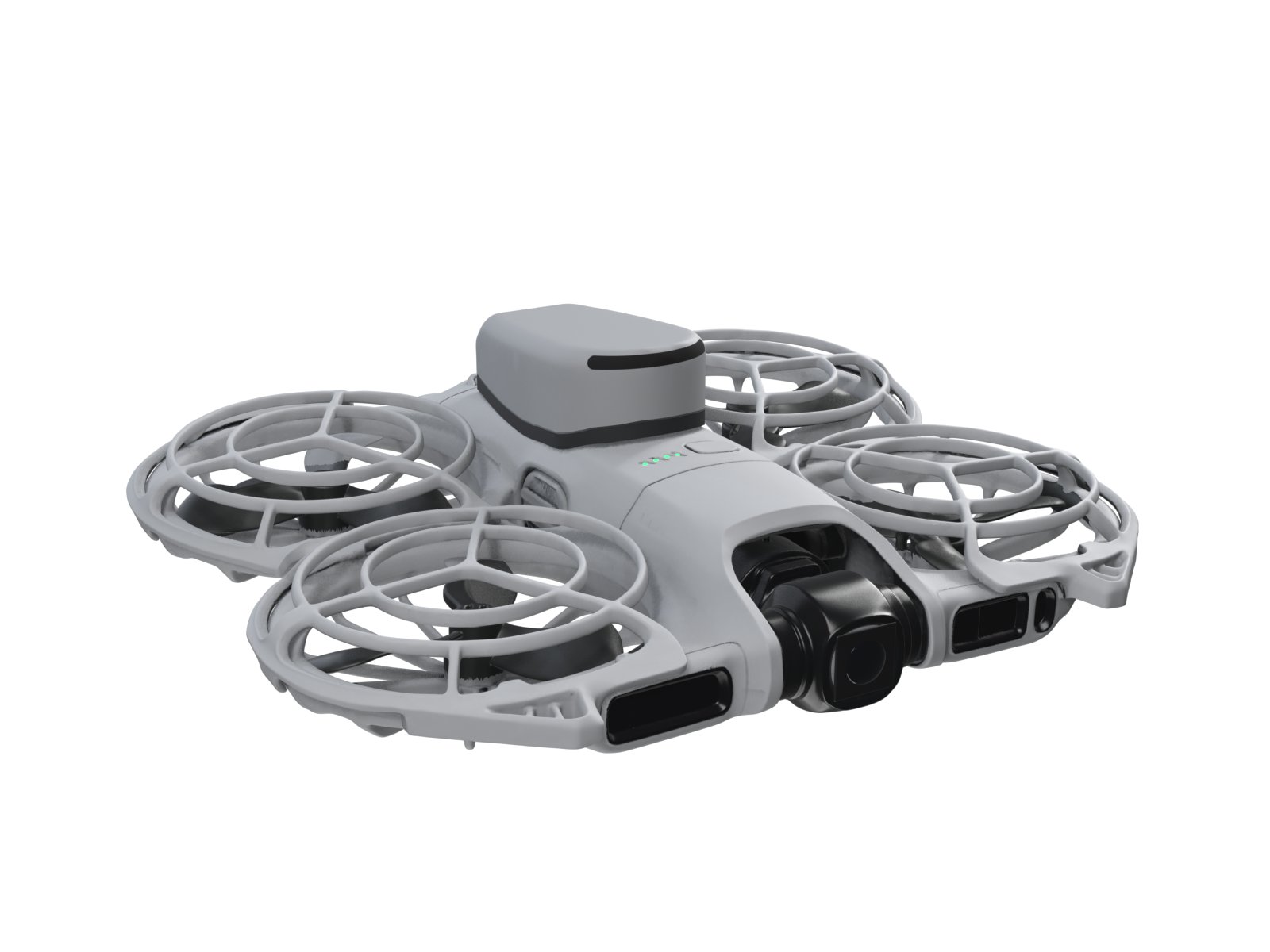
This phone-controlled mini drone uses an ESP32 microcontroller to manage four brushless motors, an MPU-6050 IMU for orientation sensing, and a lightweight lithium polymer battery. The drone receives commands over WiFi from a web interface, allowing pilots to control throttle, pitch, and roll in real time.
This guide provides a complete wiring diagram, parts list, and step-by-step assembly instructions for building the four-arm frame, motor driver circuits, and power distribution system. Included firmware handles motor PWM control, IMU data fusion, and web-based command reception, with a safe startup procedure to verify all systems before flight.
Wiring diagram

Gather all the parts
Assemble it in 6 steps
1. Make the light four-arm frame
Fit motor_fl, motor_fr, motor_bl, and motor_br into a very light 85–100 mm plastic micro-quad frame. Treat the end with motor_fl and motor_fr as the front. Fit matching clockwise and counter-clockwise propellers only after all powered tests are finished; a propeller that faces the wrong way will lift poorly.
- Keep all four motors at the same height and keep the battery near the frame centre.
- Do not fit the propellers while checking wiring or first using the phone controls — a motor can start unexpectedly and a propeller can cut skin or damage the board.
2. Build the four motor switches
For each motor, connect its positive wire to battery_1s BAT+. Connect its negative wire to that motor’s matching AO3400A Drain (D): motor_fl to mosfet_fl, motor_fr to mosfet_fr, motor_bl to mosfet_bl, and motor_br to mosfet_br. Connect every AO3400A Source (S) to battery_1s BAT- / GND. Solder one SS14 diode across each motor: its striped end (cathode) goes to the motor positive wire and its unstriped end (anode) goes to the motor negative/MOSFET-drain wire. This diode catches the electrical kick made when a motor stops.
- AO3400A parts are tiny: with the flat face and text facing you, check the seller’s pin marking before soldering. Use short, thick motor and battery wires.
- A reversed SS14 diode becomes a direct short when the battery is connected and can overheat the battery or wires.
3. Wire the ESP32 motor controls
Connect GPIO25 through gate_r_fl (100 Ω) to mosfet_fl Gate (G), GPIO26 through gate_r_fr to mosfet_fr Gate (G), GPIO27 through gate_r_bl to mosfet_bl Gate (G), and GPIO32 through gate_r_br to mosfet_br Gate (G). For each MOSFET gate, connect its matching 100 kΩ resistor to GND: pulldown_fl, pulldown_fr, pulldown_bl, and pulldown_br. These resistors make sure every motor stays off while the ESP32 is starting.
- GPIO25 → 100 Ω → front-left gate (signal); GPIO26 → 100 Ω → front-right gate (signal); GPIO27 → 100 Ω → back-left gate (signal); GPIO32 → 100 Ω → back-right gate (signal).
- Do not connect any motor directly to an ESP32 pin — the motor current will damage the board.
4. Add the level sensor
Mount imu_1 flat at the exact centre of the frame, with its printed axis arrows pointing toward the front motors. Connect VIN → 3V3 (power), GND → GND (ground), SDA → GPIO21 (data), and SCL → GPIO22 (clock).
- Use soft foam tape to reduce vibration, but do not let the sensor move relative to the frame.
- Make sure VIN and GND are not swapped — swapped power can damage the sensor.
5. Connect the battery, charger, and 3.3 V supply
Connect battery_1s BAT+ to regulator_3v3 VIN and battery_1s BAT- to regulator_3v3 GND. Connect regulator_3v3 VOUT → ESP32 3V3 (power) and keep its GND connected to the shared GND (ground). Plug the battery into charger_1s BAT, and use only the charger’s USB socket for charging. The battery positive also feeds all four motor positive wires.
- Set the regulator output to exactly 3.3 V with a multimeter before connecting it to the ESP32. Keep the charger and regulator close to the battery connection.
- Never connect the full 1-cell battery directly to the ESP32 3V3 pin — a fully charged battery can be 4.2 V and can damage it. Never charge a swollen, punctured, or hot LiPo battery.
6. Do the safe first power test
Leave all propellers off. Plug the ESP32 into USB, press Deploy in Schematik, then power the quad from its battery. On the phone, join Wi-Fi network MicroQuad using password flysafe1, then open 192.168.4.1 in the phone browser. Press ARM and use very small throttle steps to confirm each motor is in the expected corner; press STOP after each test.
- If a motor spins in the wrong direction for its propeller, reverse that motor’s two wires at the motor. Keep the model secured on the bench for this test.
- The phone page stops the motors if commands stop arriving for one second, but it is not a substitute for removing propellers during setup. Test outdoors in an open area only after the propellers are fitted.
Review all connections
1. Connections between "imu_1" and "ESP32"
2. Connections between "battery_1s" and "ESP32"
3. Connections between "motor_fl" and "ESP32"
4. Connections between "motor_fr" and "ESP32"
5. Connections between "motor_bl" and "ESP32"
6. Connections between "motor_br" and "ESP32"
7. Connections between "mosfet_fl" and "ESP32"
8. Connections between "mosfet_fr" and "ESP32"
9. Connections between "mosfet_bl" and "ESP32"
10. Connections between "mosfet_br" and "ESP32"
11. Connections between "gate_r_fl" and "ESP32"
12. Connections between "gate_r_fr" and "ESP32"
13. Connections between "gate_r_bl" and "ESP32"
14. Connections between "gate_r_br" and "ESP32"
15. Connections between "pulldown_fl" and "ESP32"
16. Connections between "pulldown_fr" and "ESP32"
17. Connections between "pulldown_bl" and "ESP32"
18. Connections between "pulldown_br" and "ESP32"
19. Connections between "diode_fl" and "ESP32"
20. Connections between "diode_fr" and "ESP32"
21. Connections between "diode_bl" and "ESP32"
22. Connections between "diode_br" and "ESP32"
23. Connections between "regulator_3v3" and "ESP32"
24. Connections between "charger_1s" and "ESP32"
Deploy the firmware
#include <Arduino.h>
#include <Wire.h>
#include <WiFi.h>
#include <WebServer.h>
#include <MPU6050.h>


// Forward declarations
int clampPwm(int value);
void motorWrite(int fl, int fr, int bl, int br);
void stopMotors();
void updateImu();
void updateMotors();
void handleCommand();

constexpr int MOTOR_FL_PIN = 25;
constexpr int MOTOR_FR_PIN = 26;
constexpr int MOTOR_BL_PIN = 27;
constexpr int MOTOR_BR_PIN = 32;
constexpr int I2C_SDA_PIN = 21;
constexpr int I2C_SCL_PIN = 22;
constexpr int PWM_FREQ = 20000;
constexpr int PWM_RESOLUTION = 8;
constexpr int PWM_MAX = 255;
constexpr int MOTOR_FL_CHANNEL = 0;
constexpr int MOTOR_FR_CHANNEL = 1;
constexpr int MOTOR_BL_CHANNEL = 2;
constexpr int MOTOR_BR_CHANNEL = 3;
constexpr uint32_t COMMAND_TIMEOUT_MS = 1000;

WebServer server(80);
MPU6050 imu;

bool armed = false;
int throttleCommand = 0;
int pitchCommand = 0;
int rollCommand = 0;
uint32_t lastCommandMs = 0;
uint32_t lastImuMs = 0;
float pitchDeg = 0.0f;
float rollDeg = 0.0f;

const char PAGE[] PROGMEM = R"rawliteral(
<!doctype html><html><head><meta name="viewport" content="width=device-width,initial-scale=1"><style>
body{font-family:Arial;text-align:center;background:#18202a;color:#fff;margin:0;padding:18px}button{font-size:20px;margin:7px;padding:16px 20px;border-radius:10px;border:0}#arm{background:#28a745;color:white}#stop{background:#d33;color:white}.row{display:flex;justify-content:center;gap:8px;flex-wrap:wrap}.hint{color:#cbd5e1}
</style></head><body><h2>Micro Quad Control</h2><p class="hint">Remove propellers for the first test.</p>
<div class="row"><button id="arm" onclick="send('arm')">ARM</button><button id="stop" onclick="send('stop')">STOP</button></div>
<h3>Throttle</h3><div class="row"><button onclick="send('t+20')">+20</button><button onclick="send('t-20')">-20</button></div>
<h3>Lean direction</h3><div class="row"><button onclick="send('r-15')">LEFT</button><button onclick="send('p+15')">FORWARD</button><button onclick="send('r+15')">RIGHT</button></div><div class="row"><button onclick="send('p-15')">BACK</button><button onclick="send('center')">LEVEL</button></div>
<p id="s">Connecting...</p><script>function send(c){fetch('/cmd?c='+encodeURIComponent(c)).then(r=>r.text()).then(t=>document.getElementById('s').textContent=t).catch(()=>document.getElementById('s').textContent='Connection lost - motors will stop');}setInterval(()=>send('keep'),400);</script></body></html>
)rawliteral";

int clampPwm(int value) { return constrain(value, 0, PWM_MAX); }
void motorWrite(int fl, int fr, int bl, int br) {
  ledcWrite(MOTOR_FL_CHANNEL, clampPwm(fl)); ledcWrite(MOTOR_FR_CHANNEL, clampPwm(fr));
  ledcWrite(MOTOR_BL_CHANNEL, clampPwm(bl)); ledcWrite(MOTOR_BR_CHANNEL, clampPwm(br));
}
void stopMotors() { motorWrite(0, 0, 0, 0); }

void updateImu() {
  uint32_t now = millis();
  float dt = (lastImuMs == 0) ? 0.01f : (now - lastImuMs) / 1000.0f;
  lastImuMs = now;
  int16_t ax, ay, az, gx, gy, gz;
  imu.getMotion6(&ax, &ay, &az, &gx, &gy, &gz);
  float accelRoll = atan2f((float)ay, (float)az) * 57.2958f;
  float accelPitch = atan2f(-(float)ax, sqrtf((float)ay * ay + (float)az * az)) * 57.2958f;
  rollDeg = 0.98f * (rollDeg + ((float)gx / 131.0f) * dt) + 0.02f * accelRoll;
  pitchDeg = 0.98f * (pitchDeg + ((float)gy / 131.0f) * dt) + 0.02f * accelPitch;
}

void updateMotors() {
  if (!armed || millis() - lastCommandMs > COMMAND_TIMEOUT_MS) { armed = false; stopMotors(); return; }
  float pitchError = (float)pitchCommand / 10.0f - pitchDeg;
  float rollError = (float)rollCommand / 10.0f - rollDeg;
  int pitchCorrection = constrain((int)(pitchError * 3.0f), -35, 35);
  int rollCorrection = constrain((int)(rollError * 3.0f), -35, 35);
  motorWrite(throttleCommand - pitchCorrection - rollCorrection,
             throttleCommand - pitchCorrection + rollCorrection,
             throttleCommand + pitchCorrection - rollCorrection,
             throttleCommand + pitchCorrection + rollCorrection);
}

void handleCommand() {
  String c = server.arg("c");
  lastCommandMs = millis();
  if (c == "arm") { armed = true; throttleCommand = 0; pitchCommand = 0; rollCommand = 0; }
  else if (c == "stop") { armed = false; throttleCommand = 0; }
  else if (c == "center") { pitchCommand = 0; rollCommand = 0; }
  else if (c.startsWith("t")) throttleCommand = constrain(throttleCommand + c.substring(1).toInt(), 0, 210);
  else if (c.startsWith("p")) pitchCommand = constrain(pitchCommand + c.substring(1).toInt(), -80, 80);
  else if (c.startsWith("r")) rollCommand = constrain(rollCommand + c.substring(1).toInt(), -80, 80);
  String reply = armed ? "ARMED | throttle " + String(throttleCommand) + " | pitch " + String(pitchDeg,1) + " | roll " + String(rollDeg,1) : "STOPPED";
  server.send(200, "text/plain", reply);
}

void setup() {
  Serial.begin(115200);
  Wire.begin(I2C_SDA_PIN, I2C_SCL_PIN);
  imu.initialize();
  ledcSetup(MOTOR_FL_CHANNEL, PWM_FREQ, PWM_RESOLUTION);
  ledcSetup(MOTOR_FR_CHANNEL, PWM_FREQ, PWM_RESOLUTION);
  ledcSetup(MOTOR_BL_CHANNEL, PWM_FREQ, PWM_RESOLUTION);
  ledcSetup(MOTOR_BR_CHANNEL, PWM_FREQ, PWM_RESOLUTION);
  ledcAttachPin(MOTOR_FL_PIN, MOTOR_FL_CHANNEL); ledcAttachPin(MOTOR_FR_PIN, MOTOR_FR_CHANNEL);
  ledcAttachPin(MOTOR_BL_PIN, MOTOR_BL_CHANNEL); ledcAttachPin(MOTOR_BR_PIN, MOTOR_BR_CHANNEL);
  stopMotors();
  WiFi.mode(WIFI_AP);
  WiFi.softAP("MicroQuad", "flysafe1");
  server.on("/", [](){ server.send_P(200, "text/html", PAGE); });
  server.on("/cmd", handleCommand);
  server.begin();
}
void loop() {
  server.handleClient();
  updateImu();
  updateMotors();
  delay(5);
}
Remix this project
Make it yours in one click
Open a full copy of this project in your own Schematik workspace — diagram, code, parts, and assembly steps included. Swap the sensor, add features, or redesign the whole thing with AI. The author's original stays untouched.