Community project
Private Wi-Fi Security Camera
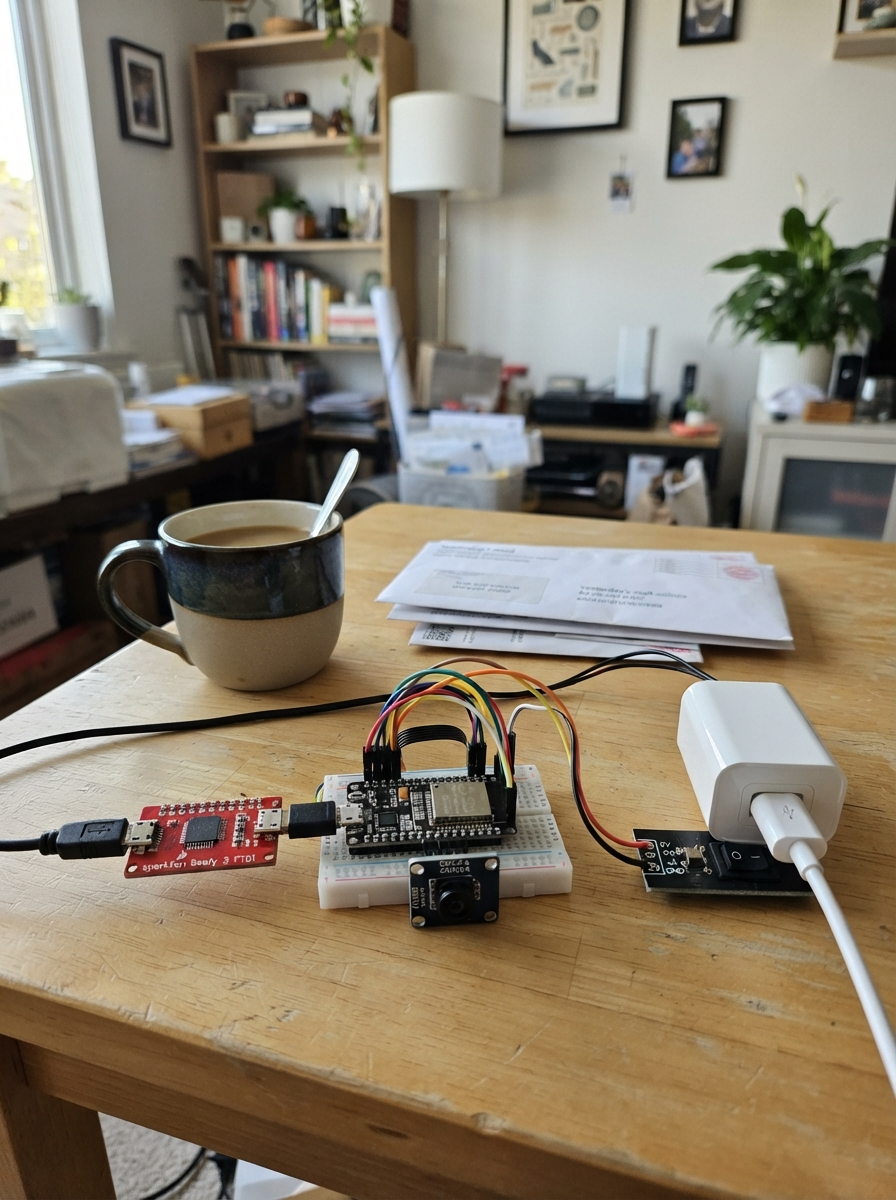
Build a private Wi-Fi security camera using an ESP32 microcontroller and OV2640 camera module. The camera connects to a home Wi-Fi network and serves a live video feed through a password-protected web page accessible from any browser on the same network. If the home network is unavailable, the camera automatically creates its own fallback access point.
This guide provides a complete parts list, wiring diagram for connecting the camera module and power supply to the ESP32, step-by-step assembly instructions, and ready-to-flash firmware with HTTP basic authentication. You'll use the SparkFun Beefy 3 FTDI programmer to load the code onto the ESP32, then access the camera feed by opening the private camera page in a web browser.
Wiring diagram

Gather all the parts
Assemble it in 4 steps
1. Power the camera safely
With the wall supply unplugged, connect the USB-C breakout VBUS pad to the ESP32-CAM 5V pin (power) and its GND pad to an ESP32-CAM GND pin (ground). Plug the regulated 5 V wall supply into the breakout only after checking both wires.
- Use short, firm power wires. The camera can restart if a thin or loose wire causes the 5 V power to dip.
- Keep the OV2640 camera ribbon fully inserted and straight in its connector.
- Do not connect this 5 V supply to the ESP32-CAM 3V3 pin — that can damage the board.
- Do not let bare VBUS and GND pads touch; that creates a short circuit.
2. Connect the programmer for flashing
With power off, connect the programmer TXO to ESP32-CAM U0R/GPIO3 (data), programmer RXI to ESP32-CAM U0T/GPIO1 (data), and programmer GND to ESP32-CAM GND (ground). For flashing only, add a jumper from ESP32-CAM GPIO0 to GND, then power the ESP32-CAM from its regulated 5 V supply.
- The two data wires cross over: TXO goes to U0R, and RXI goes to U0T.
- The programmer uses 3.3 V data signals. The separate wall supply provides the camera board's 5 V power.
- Keep GPIO0 connected to GND only while flashing. If it stays connected, the camera program will not start normally after reset.
- Make sure programmer GND and ESP32-CAM GND are connected; without a shared ground, the data wires cannot communicate reliably.
3. Flash and restart in camera mode
Use Schematik’s Deploy button while GPIO0 is connected to GND. When deployment finishes, remove the GPIO0-to-GND jumper, then press the ESP32-CAM RST button or briefly turn its 5 V power off and back on. Leave the TXO, RXI, and GND connections in place if you want to see its messages.
- Open the serial output at 115200 baud. It will print the router-assigned address as “Camera ready. Open http://...” when it joins TIMA_Terminal-2.4G.
- The code already contains the supplied Wi-Fi name and password; the router, not the firmware, chooses the local address.
- Do not use a guessed or saved camera address. Read the address printed after this boot because DHCP can assign a different address later.
- If the board repeatedly restarts, unplug power and recheck the 5V and GND wires before continuing.
4. Open the private camera page
On a phone or computer connected to TIMA_Terminal-2.4G, type the complete http address printed in the serial output into Chrome. Enter the configured camera username and password when Chrome asks, then the page will show updated camera images. If home Wi-Fi fails, join ESP32-CAM-Private using its firmware password and open the fallback address printed by the board instead.
- The router assigns the normal local address automatically; there is no IP address hard-coded in this firmware.
- Change the browser login password and fallback-network password before putting the camera in regular use.
- Do not set up router port forwarding or expose this camera to the public internet; keep it available only inside your local network.
- Do not share screenshots that show Wi-Fi or camera passwords.
Review all connections
1. Connections between "esp32-security-camera-beefy3-programmer-1" and "ESP32"
2. Connections between "esp32-security-camera-regulated-5v-supply-1" and "ESP32"
3. Connections between "esp32-security-camera-usb-c-power-breakout-1" and "ESP32"
Deploy the firmware
#include <Arduino.h>
#include "esp_camera.h"
#include <WiFi.h>
#include <WebServer.h>

// Your 2.4 GHz Wi-Fi network. The router assigns the camera IP address by DHCP.

// Forward declarations
bool requireLogin();
void handleCameraPage();
void handleCapture();
bool connectToWiFi();
void startFallbackAccessPoint();
bool startCamera();

const char* WIFI_SSID = "TIMA_Terminal-2.4G";
const char* WIFI_PASSWORD = "Tima.771995";

// Browser login. Change these before placing the camera where others can reach it.
const char* CAMERA_USER = "admin";
const char* CAMERA_PASSWORD = "admin";

// Used only when the home Wi-Fi cannot be reached within 20 seconds.
const char* FALLBACK_AP_SSID = "ESP32-CAM-Private";
const char* FALLBACK_AP_PASSWORD = "camera-fallback-2026";

// AI Thinker ESP32-CAM OV2640 camera pins.
#define PWDN_GPIO_NUM     32
#define RESET_GPIO_NUM    -1
#define XCLK_GPIO_NUM      0
#define SIOD_GPIO_NUM     26
#define SIOC_GPIO_NUM     27
#define Y9_GPIO_NUM       35
#define Y8_GPIO_NUM       34
#define Y7_GPIO_NUM       39
#define Y6_GPIO_NUM       36
#define Y5_GPIO_NUM       21
#define Y4_GPIO_NUM       19
#define Y3_GPIO_NUM       18
#define Y2_GPIO_NUM        5
#define VSYNC_GPIO_NUM    25
#define HREF_GPIO_NUM     23
#define PCLK_GPIO_NUM     22

WebServer server(80);

bool requireLogin() {
  if (server.authenticate(CAMERA_USER, CAMERA_PASSWORD)) {
    return true;
  }
  server.requestAuthentication();
  return false;
}

void handleCameraPage() {
  if (!requireLogin()) return;

  server.send(200, "text/html",
    "<!doctype html><html><head>"
    "<meta name='viewport' content='width=device-width,initial-scale=1'>"
    "<title>ESP32-CAM</title>"
    "<style>body{margin:0;padding:20px;background:#101418;color:#f5f7fa;font-family:Arial,sans-serif;text-align:center}"
    "img{display:block;width:100%;max-width:640px;margin:16px auto;border-radius:10px;background:#222}"
    "p{color:#b9c3cc}</style></head><body>"
    "<h1>ESP32 Security Camera</h1><p>Live image updates about once per second.</p>"
    "<img id='cameraImage' src='/capture' alt='Camera image'>"
    "<script>const image=document.getElementById('cameraImage');"
    "setInterval(()=>{image.src='/capture?time='+Date.now();},800);</script>"
    "</body></html>"
  );
}

void handleCapture() {
  if (!requireLogin()) return;

  camera_fb_t* frame = esp_camera_fb_get();
  if (frame == nullptr) {
    Serial.println("Camera capture failed");
    server.send(503, "text/plain", "Camera capture failed");
    return;
  }

  server.sendHeader("Cache-Control", "no-store, no-cache, must-revalidate");
  server.setContentLength(frame->len);
  server.send(200, "image/jpeg", "");
  server.sendContent(reinterpret_cast<const char*>(frame->buf), frame->len);

  esp_camera_fb_return(frame);
}

bool connectToWiFi() {
  WiFi.mode(WIFI_STA);
  WiFi.begin(WIFI_SSID, WIFI_PASSWORD);
  Serial.print("Connecting to Wi-Fi");

  const unsigned long startedAt = millis();
  while (WiFi.status() != WL_CONNECTED && millis() - startedAt < 20000UL) {
    delay(500);
    Serial.print('.');
  }
  Serial.println();

  if (WiFi.status() == WL_CONNECTED) {
    Serial.print("Connected to Wi-Fi. DHCP assigned IP: ");
    Serial.println(WiFi.localIP());
    Serial.print("Camera ready. Open http://");
    Serial.println(WiFi.localIP());
    Serial.println("OK: NETWORK READY");
    return true;
  }

  WiFi.disconnect(true);
  Serial.println("Wi-Fi connection failed after 20 seconds.");
  return false;
}

void startFallbackAccessPoint() {
  WiFi.mode(WIFI_AP);
  if (WiFi.softAP(FALLBACK_AP_SSID, FALLBACK_AP_PASSWORD)) {
    Serial.print("Fallback private Wi-Fi started: ");
    Serial.println(FALLBACK_AP_SSID);
    Serial.print("Camera ready. Join that Wi-Fi, then open http://");
    Serial.println(WiFi.softAPIP());
  } else {
    Serial.println("Fallback Wi-Fi could not be started.");
  }
}

bool startCamera() {
  camera_config_t config = {};
  config.ledc_channel = LEDC_CHANNEL_0;
  config.ledc_timer = LEDC_TIMER_0;
  config.pin_d0 = Y2_GPIO_NUM;
  config.pin_d1 = Y3_GPIO_NUM;
  config.pin_d2 = Y4_GPIO_NUM;
  config.pin_d3 = Y5_GPIO_NUM;
  config.pin_d4 = Y6_GPIO_NUM;
  config.pin_d5 = Y7_GPIO_NUM;
  config.pin_d6 = Y8_GPIO_NUM;
  config.pin_d7 = Y9_GPIO_NUM;
  config.pin_xclk = XCLK_GPIO_NUM;
  config.pin_pclk = PCLK_GPIO_NUM;
  config.pin_vsync = VSYNC_GPIO_NUM;
  config.pin_href = HREF_GPIO_NUM;
  config.pin_sccb_sda = SIOD_GPIO_NUM;
  config.pin_sccb_scl = SIOC_GPIO_NUM;
  config.pin_pwdn = PWDN_GPIO_NUM;
  config.pin_reset = RESET_GPIO_NUM;
  config.xclk_freq_hz = 20000000;
  config.pixel_format = PIXFORMAT_JPEG;
  config.frame_size = FRAMESIZE_VGA;
  config.jpeg_quality = 12;
  config.fb_count = 1;

  const esp_err_t result = esp_camera_init(&config);
  if (result != ESP_OK) {
    Serial.printf("Camera initialization failed: 0x%X\n", result);
    return false;
  }

  Serial.println("Camera initialized");
  Serial.println("OK: CAMERA INITIALIZED");
  return true;
}

void setup() {
  Serial.begin(115200);
  delay(3000);

  Serial.println();
  Serial.println("==============================");
  Serial.println("ESP32-CAM starting");
  Serial.println("==============================");

  if (!startCamera()) {
    Serial.println("Check that the OV2640 ribbon is fully seated and the board is an AI Thinker ESP32-CAM.");
    return;
  }

  if (!connectToWiFi()) {
    startFallbackAccessPoint();
  }

  server.on("/", HTTP_GET, handleCameraPage);
  server.on("/capture", HTTP_GET, handleCapture);
  server.begin();
  Serial.println("Browser camera server started");
}

void loop() {
  server.handleClient();
}
Remix this project
Make it yours in one click
Open a full copy of this project in your own Schematik workspace — diagram, code, parts, and assembly steps included. Swap the sensor, add features, or redesign the whole thing with AI. The author's original stays untouched.