Community project
双色温摄影补光灯
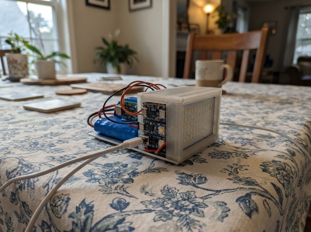
This dual-color temperature photography fill light delivers professional-grade illumination from a compact, battery-powered platform. Combining 100W warm white (3000K) and cool white (5600K) LED panels with independent PWM control, the system lets photographers dial in the exact color temperature needed for any scene. Power comes from a 2S 18650 battery pack with USB-C Power Delivery support, while an ESP32-S3 microcontroller manages brightness, color mixing, thermal monitoring, and fan speed through a rotary encoder and OLED display interface.
This guide provides a complete parts list, wiring diagram, and step-by-step assembly instructions covering battery pack preparation, power distribution, LED driver configuration, and firmware setup. Builders will learn how to integrate a USB Power Delivery sink module for flexible charging, configure constant-current LED drivers for flicker-free output, and program the ESP32-S3 to deliver intuitive on-set control. Thermal management and safety checks ensure reliable operation in demanding production environments.
Wiring diagram

Gather all the parts
Assemble it in 9 steps
1. 准备工具和材料
准备好以下材料:2节容量匹配的18650电芯(推荐Samsung 30Q或Sony VTC6,3000mAh以上)、2S电池座(带电芯熔断保险丝)、MP2762A模块(淘宝关键词:MP2762A 2S充电模块)、HUSB238 PD模块(Adafruit #5807或国产兼容板)、5.5/2.1mm DC母座、AMS1117-3.3模块、LM2596-5V模块、两路XL4016(或LM2596)恒流Buck驱动模块、100W 3000K暖白COB LED、100W 5600K冷白COB LED、大铝合金散热片+导热硅脂、40mm 5V风扇、ESP32-S3 DevKitC-1开发板、KY-040旋转编码器模块、SSD1306 0.96寸OLED、N-MOSFET(IRLZ44N或2N7000,用于风扇PWM控制)。
- 两颗18650容量差异不超过50mAh,否则2S串联时会过充/过放其中一节
- 所有大电流走线(VSYS、LED驱动输入)使用≥1mm²硅胶线
- 100W LED必须配足够大的散热片,无散热片严禁通电
2. 组装2S电池包
将两节18650装入2S串联电池座。BAT+接电池组正极(约8.4V满电),BAT-接负极。用硅胶热缩管包裹电池组。在电池侧面粘贴10kΩ NTC热敏电阻(导热胶固定),NTC的两根引线稍后接MP2762A的NTC引脚和GND。
- 使用专用点焊机而非烙铁焊接18650引片,避免过热损坏电芯
- 严禁将2S电池正负极短路
- 安装前确认单节电压在2.5V以上,低于此电压需先用单节充电器激活
3. 电源主链路布线
按如下顺序连接电源主干路: ① HUSB238模块的VOUT引脚 → Schottky二极管(1N5822,阴极朝前) → 主电源节点"VSYS_IN" ② DC母座正极DC+ → Schottky二极管(1N5822,阴极朝前) → 同一主电源节点"VSYS_IN" ③ 主节点"VSYS_IN" → MP2762A模块的VIN引脚 ④ 电池包BAT+ → MP2762A的BAT+;电池包BAT- → MP2762A的BAT- ⑤ MP2762A的VSYS输出 → 各负载输入(暖色驱动模块VIN+、冷色驱动模块VIN+、LM2596 VIN、AMS1117 VIN) ⑥ 所有模块GND → 公共GND平面
- 两个Schottky二极管做OR-ing,防止DC和PD两路互相倒灌
- MP2762A VIN最高21V,不要接超过20V的适配器
4. 安装LED和散热片
在铝合金散热片上均匀涂抹导热硅脂,将100W 3000K暖白COB LED和100W 5600K冷白COB LED固定于散热片。LED+和LED-分别用硅胶线引出。安装40mm风扇于散热片侧面,对准散热鳍片方向吹风。LED引线从散热片侧面穿出,分别接各自的恒流驱动模块LED+/LED-输出端。
- COB LED工作电压约30-36V、电流约3A,严禁直接接电池或VSYS,必须通过恒流驱动模块
- 散热片安装后,LED金属背板电气上通常与散热片导通,注意绝缘
5. 配置恒流驱动模块
两块XL4016/LM2596恒流模块需要单独调整输出恒流值: ① 先不连LED,将模块VIN+接VSYS,VIN-接GND ② 在LED+和LED-之间串联电流表,同时LED+和LED-接一个功率型负载电阻(约10Ω 50W代替LED) ③ 上电,调节模块上的电位器,使电流表读数达到目标值(100W LED约3A;若想保守工作可设2A) ④ 断电,接上真实LED,此后不再调整电位器 两路恒流值分别调好后,再接DIM引脚:DIM信号线接驱动模块的PWM调光输入。
- XL4016模块通常有CC和CV两个电位器,CC电位器调恒流,CV电位器调输出电压上限,先调高CV再调CC
- 如驱动模块无DIM引脚,可在驱动模块输入的GND侧串一个N-MOSFET(漏极接模块VIN-,源极接系统GND,栅极接MCU PWM)实现PWM调光
6. 风扇N-MOSFET驱动电路
在ESP32-S3 GPIO38和风扇之间加N-MOSFET驱动电路: - MOSFET源极(S)→ GND - MOSFET漏极(D)→ 风扇GND引线 - MOSFET栅极(G)← 1kΩ电阻 ← GPIO38 - 风扇VCC → LM2596 5V输出 - 在风扇电源引脚并联100µF滤波电容(注意极性) - 如使用带转速反馈的4线风扇,可将TACHO脚额外连至一个GPIO读取转速(选做)
- IRLZ44N在3.3V栅极驱动下完全导通,2N7000也可以但仅适合<200mA小风扇
7. 连接ESP32-S3控制部分
按以下接线连接控制电路(所有信号都是3.3V): **I2C总线(GPIO8=SDA, GPIO9=SCL,共享3条设备)** - OLED SDA→GPIO8, SCL→GPIO9, VCC→3.3V, GND→GND - MP2762A SDA→GPIO8, SCL→GPIO9 - HUSB238 SDA→GPIO8, SCL→GPIO9, VIN→3.3V, GND→GND - I2C总线上加4.7kΩ上拉电阻(SDA到3.3V一个,SCL到3.3V一个) **编码器 (GPIO40/41/42)** - KY-040 VCC→3.3V, GND→GND - CLK→GPIO40, DT→GPIO41, SW→GPIO42 **PWM调光** - 暖色驱动模块DIM→GPIO14 - 冷色驱动模块DIM→GPIO21 **ESP32-S3供电** - AMS1117-3.3的VOUT→ESP32 3V3引脚(或通过USB供电调试用)
- 调试阶段可直接用USB给ESP32供电,不必接AMS1117,待固件验证OK后再改用AMS1117独立供电
8. 固件烧录和调试
将ESP32-S3通过USB连接到电脑,打开Schematik,点击Deploy按钮烧录固件。烧录成功后: ① 先不接LED,仅上电测试OLED是否正常显示 ② 旋转编码器确认亮度/色温数值变化 ③ 短按编码器确认在亮度模式和色温模式之间切换 ④ 长按(>0.6秒)确认灯开/关切换 ⑤ 用示波器或PWM频率测量工具确认GPIO14和GPIO21输出25kHz PWM ⑥ 最后连接LED驱动模块和LED,观察调光效果
- Serial Monitor波特率115200,打印HUSB238检测结果和错误信息
9. 整机组装和安全检查
完成调试后进行整机组装: ① 将所有模块固定在灯体内(建议3mm铝板或亚克力背板) ② 电池组用魔术贴可拆卸固定,方便热拔插换电 ③ 外露金属部分注意绝缘 ④ 最终检查:用万用表测量VSYS电压(应为7.0~8.4V),3.3V轨,5V轨各项正常 ⑤ 用PD充电器插入USB-C口,观察MP2762A是否开始充电(OLED可额外显示充电状态)
- 整机通电前用万用表核查VSYS没有对GND短路
- 100W LED工作时散热片温度可能超过60°C,注意防烫
Review all connections
1. Connections between "dc_jack" and "ESP32"
2. Connections between "husb238" and "ESP32"
3. Connections between "battery_2s" and "ESP32"
4. Connections between "ntc_bat" and "ESP32"
5. Connections between "mp2762a" and "ESP32"
6. Connections between "ldo_3v3" and "ESP32"
7. Connections between "led_driver_warm" and "ESP32"
8. Connections between "led_driver_cool" and "ESP32"
9. Connections between "oled" and "ESP32"
10. Connections between "encoder" and "ESP32"
11. Connections between "ldo_5v" and "ESP32"
12. Connections between "fan" and "ESP32"
Deploy the firmware
// ============================================================
//  Photography Fill Light Controller
//  Board  : ESP32-S3 DevKitC-1
//  Power  : 2S 18650 (7.4V) via MP2762A NVDC charger
//  PD     : HUSB238 negotiates USB-C PD (asks for 20V)
//  LED    : Two PWM Buck CC drivers — warm 3000K + cool 5600K
//  UI     : KY-040 rotary encoder + SSD1306 0.96" OLED (I2C)
//  Fan    : 5V fan via N-MOSFET, speed tracks brightness
// ============================================================

#include <Arduino.h>
#include <Wire.h>
#include <Adafruit_GFX.h>
#include <Adafruit_SSD1306.h>
#include "Adafruit_HUSB238.h"

// ── Pin definitions ──────────────────────────────────────────
#define PIN_ENC_CLK   40
#define PIN_ENC_DT    41
#define PIN_ENC_SW    42
#define PIN_PWM_WARM  14
#define PIN_PWM_COOL  21
#define PIN_FAN       38

// ── LEDC (ESP32 hardware PWM) channels ───────────────────────
#define CH_WARM  0
#define CH_COOL  1
#define CH_FAN   2
#define PWM_FREQ 25000   // 25 kHz – inaudible, good for CC modules
#define PWM_BITS 10      // 1024 steps

// ── OLED ──────────────────────────────────────────────────────
#define OLED_W    128
#define OLED_H    64
#define OLED_ADDR 0x3C

// Forward declarations
static void applyLED();
static void drawDisplay();
void IRAM_ATTR encoderISR();

Adafruit_SSD1306 display(OLED_W, OLED_H, &Wire, -1);

// ── HUSB238 ───────────────────────────────────────────────────
Adafruit_HUSB238 pd;

// ── State ─────────────────────────────────────────────────────
// UI modes: 0 = adjust brightness, 1 = adjust colour temp (CCT)
uint8_t  uiMode       = 0;
int16_t  brightness   = 80;   // 0–100%
int16_t  cct          = 50;   // 0 = full warm, 100 = full cool
bool     lightsOn     = true;

// Encoder state
volatile int8_t  encDelta     = 0;
volatile uint8_t encLastState = 0;

// Debounce
unsigned long swLastMs = 0;
bool          swWasPressed = false;

// Display dirty flag
bool displayDirty = true;

// ── Helpers ───────────────────────────────────────────────────
static void applyLED() {
    if (!lightsOn) {
        ledcWrite(CH_WARM, 0);
        ledcWrite(CH_COOL, 0);
        ledcWrite(CH_FAN,  0);
        return;
    }

    // Scale brightness (0-100) to PWM duty (0-1023)
    float bScale = brightness / 100.0f;

    // CCT: 0% warm only, 100% cool only, 50% equal blend
    float wFrac = 1.0f - (cct / 100.0f);
    float cFrac = cct / 100.0f;

    uint16_t warmDuty = (uint16_t)(bScale * wFrac * 1023);
    uint16_t coolDuty = (uint16_t)(bScale * cFrac * 1023);

    // Fan speed roughly tracks brightness (min 20% when on)
    uint16_t fanDuty  = (uint16_t)((0.20f + 0.80f * bScale) * 1023);

    ledcWrite(CH_WARM, warmDuty);
    ledcWrite(CH_COOL, coolDuty);
    ledcWrite(CH_FAN,  fanDuty);
}

static void drawDisplay() {
    display.clearDisplay();

    // ── Title / power source indicator ───────────────────────
    display.setTextSize(1);
    display.setTextColor(SSD1306_WHITE);
    display.setCursor(0, 0);
    display.print(lightsOn ? "FILL LIGHT  ON" : "FILL LIGHT OFF");

    // ── Brightness bar ────────────────────────────────────────
    display.setCursor(0, 14);
    display.print("BRI ");
    display.print(brightness);
    display.print("%");
    if (uiMode == 0) {
        display.print(" <");  // active field indicator
    }
    // Draw bar
    int barW = (brightness * 100) / 100;  // maps 0-100 to 0-100 px
    display.fillRect(0,  25, barW, 6, SSD1306_WHITE);
    display.drawRect(0,  25, 100,  6, SSD1306_WHITE);

    // ── CCT bar ───────────────────────────────────────────────
    display.setCursor(0, 35);
    int cctK = 3000 + (int)((cct / 100.0f) * 2600);  // 3000-5600 K
    display.print("CCT ");
    display.print(cctK);
    display.print("K");
    if (uiMode == 1) {
        display.print(" <");  // active field indicator
    }
    // Draw bar: left = warm, right = cool
    display.fillRect(0, 46, cct, 6, SSD1306_WHITE);  // filled = cool portion
    display.drawRect(0, 46, 100, 6, SSD1306_WHITE);

    // ── W/C split label ──────────────────────────────────────
    display.setCursor(0, 56);
    display.print("W");
    int warmPct = 100 - cct;
    int coolPct = cct;
    display.print(warmPct);
    display.print("%  C");
    display.print(coolPct);
    display.print("%");

    display.display();
}

// ── Encoder ISR ───────────────────────────────────────────────
void IRAM_ATTR encoderISR() {
    uint8_t clk = digitalRead(PIN_ENC_CLK);
    uint8_t dt  = digitalRead(PIN_ENC_DT);
    uint8_t cur = (clk << 1) | dt;
    if (cur != encLastState) {
        if (encLastState == 0b10 && cur == 0b00) encDelta++;
        if (encLastState == 0b01 && cur == 0b00) encDelta--;
        encLastState = cur;
    }
}

// ── Setup ─────────────────────────────────────────────────────
void setup() {
    Serial.begin(115200);

    // LEDC PWM
    ledcSetup(CH_WARM, PWM_FREQ, PWM_BITS);
    ledcSetup(CH_COOL, PWM_FREQ, PWM_BITS);
    ledcSetup(CH_FAN,  PWM_FREQ, PWM_BITS);
    ledcAttachPin(PIN_PWM_WARM, CH_WARM);
    ledcAttachPin(PIN_PWM_COOL, CH_COOL);
    ledcAttachPin(PIN_FAN,      CH_FAN);

    // Encoder
    pinMode(PIN_ENC_CLK, INPUT_PULLUP);
    pinMode(PIN_ENC_DT,  INPUT_PULLUP);
    pinMode(PIN_ENC_SW,  INPUT_PULLUP);
    encLastState = (digitalRead(PIN_ENC_CLK) << 1) | digitalRead(PIN_ENC_DT);
    attachInterrupt(digitalPinToInterrupt(PIN_ENC_CLK), encoderISR, CHANGE);
    attachInterrupt(digitalPinToInterrupt(PIN_ENC_DT),  encoderISR, CHANGE);

    // I2C
    Wire.begin(8, 9);   // SDA=GPIO8, SCL=GPIO9

    // OLED
    if (!display.begin(SSD1306_SWITCHCAPVCC, OLED_ADDR)) {
        Serial.println("SSD1306 init failed");
    }
    display.clearDisplay();
    display.display();

    // HUSB238 – negotiate 20V for maximum power
    if (pd.begin(0x08, &Wire)) {
        Serial.println("HUSB238 found, requesting 20V PD...");
        pd.selectVoltage(PD_20V);
    } else {
        Serial.println("HUSB238 not found (DC input assumed)");
    }

    applyLED();
    drawDisplay();
}

// ── Loop ──────────────────────────────────────────────────────
void loop() {
    // --- Encoder delta (atomic read) ---
    noInterrupts();
    int8_t delta = encDelta;
    encDelta = 0;
    interrupts();

    if (delta != 0) {
        if (uiMode == 0) {
            brightness = constrain(brightness + delta, 0, 100);
        } else {
            cct = constrain(cct + delta, 0, 100);
        }
        applyLED();
        displayDirty = true;
    }

    // --- Button (debounced) ---
    bool swPressed = (digitalRead(PIN_ENC_SW) == LOW);
    unsigned long now = millis();
    if (swPressed && !swWasPressed && (now - swLastMs > 50)) {
        swLastMs = now;
        // Short press < 600 ms: switch mode
        // Long press ≥ 600 ms: toggle on/off (handled on release)
    }
    if (!swPressed && swWasPressed) {
        unsigned long held = now - swLastMs;
        if (held < 600) {
            uiMode = 1 - uiMode;  // toggle brightness / CCT
        } else {
            lightsOn = !lightsOn;
            applyLED();
        }
        displayDirty = true;
    }
    swWasPressed = swPressed;

    // --- Display update (only when state changed) ---
    if (displayDirty) {
        drawDisplay();
        displayDirty = false;
    }

    delay(10);  // ~100 Hz poll, keeps ISR happy
}
Remix this project
Make it yours in one click
Open a full copy of this project in your own Schematik workspace — diagram, code, parts, and assembly steps included. Swap the sensor, add features, or redesign the whole thing with AI. The author's original stays untouched.