Community project
Push-Up Alarm Clock
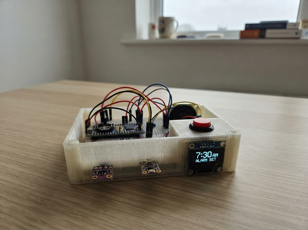
This project builds an alarm clock that won't let you hit snooze without doing push-ups. When the alarm sounds, a time-of-flight distance sensor and IMU track your body position and movement to verify that you've completed the required repetitions. The guide includes a wiring diagram, complete parts list, and step-by-step assembly instructions for connecting the ESP32, RTC, OLED display, distance sensor, IMU, speaker amplifier, and control buttons.
The firmware uses the DS3231 real-time clock to manage alarm timing, displays status on the SSD1306 OLED, and monitors push-up form using acceleration thresholds and distance measurements from the VL53L0X sensor. Six push buttons let you set the alarm time, snooze, and test the system. Once you complete the required repetitions, the alarm stops and the clock returns to normal operation.
Wiring diagram

Gather all the parts
Assemble it in 5 steps
1. Place the clock parts
For the prototype, mount the ESP32-S3 DevKitC-1, OLED, DS3231, QMI8658, VL53L0X, MAX98357A, speaker, and six buttons in or on a non-conductive enclosure. Put the OLED at the front, leave a clear round opening in front of the VL53L0X, and aim that opening toward the floor when you lower the clock during a push-up.
- Put the motion sensor and distance sensor on the same rigid front face so they travel together.
- The distance sensor needs a direct view of the floor; a grille or tinted window in front of it can prevent reliable readings.
- Do not point the VL53L0X into a mirror, very dark carpet, or a loose fabric flap — it may not get a dependable distance reading.
2. Make the shared sensor and screen wires
Connect DS3231 VIN, OLED VCC, QMI8658 VCC, and VL53L0X VIN to ESP32 3V3 (power). Connect all four GND pins to ESP32 GND (ground). Connect each module SDA pin to GPIO8 (data) and each SCL pin to GPIO9 (clock). Fit the DS3231's CR1220 backup cell in its holder with its positive face matching the holder marking.
- These four modules share the same two data wires safely because their addresses are different: OLED 0x3C, VL53L0X 0x29, DS3231 0x68, and QMI8658 0x6B.
- Keep the I2C wires short in a prototype, ideally under 20 cm.
- Use a VL53L0X breakout that explicitly supports 3.3 V logic and supply. Do not feed 5 V pull-ups into GPIO8 or GPIO9; 5 V logic can damage the ESP32-S3.
3. Wire the speaker amplifier
Connect amplifier VIN to the board 5V pin (power) and amplifier GND to board GND (ground). Connect BCLK to GPIO14 (audio clock), LRC to GPIO15 (audio timing), and DIN to GPIO16 (audio signal). Connect amplifier SPK+ to speaker POS (speaker signal) and amplifier SPK- to speaker NEG (speaker signal).
- Use a 1 W or higher 8 ohm speaker and mount it behind a front or side grille.
- Twist the two wires between the amplifier and speaker together to reduce noise.
- Never connect either speaker wire to GND — this amplifier drives both speaker wires and grounding one can damage the amplifier.
- Do not power the speaker from an ESP32 GPIO; the amplifier is the part designed to supply the needed current.
4. Wire the six control buttons
For every button, connect its GND pin to ESP32 GND (ground). Connect Setup SIGNAL to GPIO1 (setup), Up SIGNAL to GPIO2 (increase), Down SIGNAL to GPIO3 (decrease), Select SIGNAL to GPIO4 (save/next), Snooze SIGNAL to GPIO5 (five-minute pause), and Test Alarm SIGNAL to GPIO6 (start a test challenge).
- Each button has one wire to its GPIO and the other to ground because the firmware holds the GPIO high until the button is pressed.
- Label the enclosure buttons before closing it so Test Alarm is not confused with Snooze.
- The buttons do not turn off an active alarm. Snooze only pauses it for five minutes; completing ten accepted movements is the normal stop condition.
5. Power and try the prototype
Before closing the enclosure, inspect every 3V3, 5V, and GND connection. Plug the DevKit into USB-C or its USB port (power). Set the desired alarm with Setup, Up, Down, and Select, then press Test Alarm to check the challenge without waiting for morning.
- Start with the clock about 10–18 cm above a light-colored floor and lower then raise it smoothly; the display should advance only after a complete down-and-up cycle.
- If ordinary movement is counted, make the near/far floor distances farther apart in the firmware; if valid movements are missed, test with a light floor and verify the sensor opening is clear.
- Make sure VCC and GND are not swapped before USB power is connected — swapped power can permanently damage a module.
Review all connections
1. Connections between "rtc_ds3231" and "ESP32"
2. Connections between "oled" and "ESP32"
3. Connections between "imu" and "ESP32"
4. Connections between "tof" and "ESP32"
5. Connections between "amp" and "ESP32"
6. Connections between "btn_setup" and "ESP32"
7. Connections between "btn_up" and "ESP32"
8. Connections between "btn_down" and "ESP32"
9. Connections between "btn_select" and "ESP32"
10. Connections between "btn_snooze" and "ESP32"
11. Connections between "btn_test" and "ESP32"
Deploy the firmware
#include <Arduino.h>
#include <Wire.h>
#include <RTClib.h>
#include <Adafruit_GFX.h>
#include <Adafruit_SSD1306.h>
#include <Adafruit_VL53L0X.h>
#include <driver/i2s_std.h>


// Hoisted type definitions
enum ClockState { NORMAL, SET_ALARM_HOUR, SET_ALARM_MINUTE, ALARM_ACTIVE, SNOOZED, COMPLETE, SENSOR_FAULT };

enum RepState { READY, DOWN_DETECTED, LOW_CONFIRMED };


// Forward declarations
bool pressed(int pin);
void qmiWrite(uint8_t reg, uint8_t value);
bool qmiReadAccel(float &ax, float &ay, float &az);
bool beginQmi();
void beginAudio();
void playTone(uint16_t hz, uint16_t durationMs);
void updateAlarmSound();
void showFrame(const String &line1, const String &line2, const String &line3, uint8_t size1);
uint16_t readDistanceMm(bool &valid);
void resetChallenge();
void samplePushup();
void handleButtons();
void updateDisplay(const DateTime &now);

constexpr int I2C_SDA = 8;
constexpr int I2C_SCL = 9;
constexpr int I2S_BCLK = 14;
constexpr int I2S_LRCK = 15;
constexpr int I2S_DOUT = 16;
constexpr int SETUP_PIN = 1;
constexpr int UP_PIN = 2;
constexpr int DOWN_PIN = 3;
constexpr int SELECT_PIN = 4;
constexpr int SNOOZE_PIN = 5;
constexpr int TEST_PIN = 6;
constexpr uint8_t QMI_ADDR = 0x6B;
constexpr int REQUIRED_REPS = 10;
constexpr uint16_t FLOOR_NEAR_MM = 180;
constexpr uint16_t FLOOR_FAR_MM = 330;
constexpr float DOWN_ACCEL_G = 1.30f;
constexpr float UP_ACCEL_G = 1.15f;
constexpr uint32_t MIN_DOWN_MS = 220;
constexpr uint32_t MAX_REP_MS = 5000;
constexpr uint32_t SNOOZE_MS = 5UL * 60UL * 1000UL;

Adafruit_SSD1306 display(128, 64, &Wire, -1);
RTC_DS3231 rtc;
Adafruit_VL53L0X tof;
i2s_chan_handle_t txHandle = nullptr;


ClockState clockState = NORMAL;
RepState repState = READY;
int alarmHour = 7;
int alarmMinute = 0;
int reps = 0;
bool alarmPlayedToday = false;
bool rtcOk = false;
bool tofOk = false;
bool imuOk = false;
uint32_t phaseStarted = 0;
uint32_t snoozeUntil = 0;
uint32_t lastScreenSecond = 999999;
uint32_t lastAudioUpdate = 0;
uint32_t lastButtonPoll = 0;
String lastFrame;

bool pressed(int pin) {
  static uint32_t lastPress[7] = {0};
  int index = pin - 1;
  if (digitalRead(pin) == LOW && millis() - lastPress[index] > 180) {
    lastPress[index] = millis();
    return true;
  }
  return false;
}

void qmiWrite(uint8_t reg, uint8_t value) {
  Wire.beginTransmission(QMI_ADDR);
  Wire.write(reg);
  Wire.write(value);
  Wire.endTransmission();
}

bool qmiReadAccel(float &ax, float &ay, float &az) {
  Wire.beginTransmission(QMI_ADDR);
  Wire.write(0x35);
  if (Wire.endTransmission(false) != 0 || Wire.requestFrom(QMI_ADDR, (uint8_t)6) != 6) return false;
  int16_t x = (int16_t)(Wire.read() | (Wire.read() << 8));
  int16_t y = (int16_t)(Wire.read() | (Wire.read() << 8));
  int16_t z = (int16_t)(Wire.read() | (Wire.read() << 8));
  // QMI8658 configured for +/-4 g: 8192 counts per g.
  ax = x / 8192.0f;
  ay = y / 8192.0f;
  az = z / 8192.0f;
  return true;
}

bool beginQmi() {
  Wire.beginTransmission(QMI_ADDR);
  Wire.write(0x00);
  if (Wire.endTransmission(false) != 0 || Wire.requestFrom(QMI_ADDR, (uint8_t)1) != 1) return false;
  uint8_t id = Wire.read();
  if (id != 0x05) return false;
  qmiWrite(0x02, 0x60); // accelerometer enabled, 1 kHz interface mode.
  qmiWrite(0x03, 0x44); // +/-4 g, 125 Hz output data rate.
  delay(10);
  return true;
}

void beginAudio() {
  i2s_chan_config_t chanCfg = I2S_CHANNEL_DEFAULT_CONFIG(I2S_NUM_AUTO, I2S_ROLE_MASTER);
  i2s_new_channel(&chanCfg, &txHandle, nullptr);
  i2s_std_config_t stdCfg = {
    .clk_cfg = I2S_STD_CLK_DEFAULT_CONFIG(16000),
    .slot_cfg = I2S_STD_MSB_SLOT_DEFAULT_CONFIG(I2S_DATA_BIT_WIDTH_16BIT, I2S_SLOT_MODE_MONO),
    .gpio_cfg = {
      .mclk = I2S_GPIO_UNUSED,
      .bclk = (gpio_num_t)I2S_BCLK,
      .ws = (gpio_num_t)I2S_LRCK,
      .dout = (gpio_num_t)I2S_DOUT,
      .din = I2S_GPIO_UNUSED,
      .invert_flags = { .mclk_inv = false, .bclk_inv = false, .ws_inv = false }
    }
  };
  i2s_channel_init_std_mode(txHandle, &stdCfg);
  i2s_channel_enable(txHandle);
}

void playTone(uint16_t hz, uint16_t durationMs) {
  if (!txHandle) return;
  const int samples = 16000 * durationMs / 1000;
  int16_t sample;
  size_t written;
  for (int i = 0; i < samples; i++) {
    sample = (int16_t)(sinf(2.0f * PI * hz * i / 16000.0f) * 12000.0f);
    i2s_channel_write(txHandle, &sample, sizeof(sample), &written, 10);
  }
}

void updateAlarmSound() {
  if (clockState != ALARM_ACTIVE || millis() - lastAudioUpdate < 900) return;
  lastAudioUpdate = millis();
  uint16_t tone = (reps < 3) ? 700 : (reps < 7 ? 950 : 1200);
  playTone(tone, 180);
  delay(35);
  playTone(tone + 180, 180);
}

void showFrame(const String &line1, const String &line2, const String &line3, uint8_t size1 = 1) {
  String frame = line1 + "|" + line2 + "|" + line3 + "|" + String(size1);
  if (frame == lastFrame) return;
  lastFrame = frame;
  display.clearDisplay();
  display.setTextColor(SSD1306_WHITE);
  display.setTextSize(size1);
  display.setCursor(0, 0);
  display.println(line1);
  display.setTextSize(1);
  display.setCursor(0, 30);
  display.println(line2);
  display.setCursor(0, 48);
  display.println(line3);
  display.display();
}

uint16_t readDistanceMm(bool &valid) {
  VL53L0X_RangingMeasurementData_t measurement;
  tof.rangingTest(&measurement, false);
  valid = measurement.RangeStatus == 0;
  return valid ? measurement.RangeMilliMeter : 8190;
}

void resetChallenge() {
  reps = 0;
  repState = READY;
  phaseStarted = millis();
  clockState = ALARM_ACTIVE;
  lastFrame = "";
}

void samplePushup() {
  if (clockState != ALARM_ACTIVE || !imuOk || !tofOk) return;
  float ax, ay, az;
  bool rangeValid = false;
  uint16_t range = readDistanceMm(rangeValid);
  if (!qmiReadAccel(ax, ay, az) || !rangeValid) return;
  float magnitude = sqrtf(ax * ax + ay * ay + az * az);
  uint32_t elapsed = millis() - phaseStarted;

  if (repState == READY) {
    // A real downward stroke has impact/motion and reaches close to the floor.
    if (magnitude >= DOWN_ACCEL_G && range <= FLOOR_NEAR_MM) {
      repState = DOWN_DETECTED;
      phaseStarted = millis();
    }
  } else if (repState == DOWN_DETECTED) {
    // Staying near the floor briefly rejects a fast shake or sensor glitch.
    if (range <= FLOOR_NEAR_MM && elapsed >= MIN_DOWN_MS) {
      repState = LOW_CONFIRMED;
    } else if (elapsed > 1500 || range > FLOOR_FAR_MM) {
      repState = READY;
    }
  } else if (repState == LOW_CONFIRMED) {
    // Count only after rising away from the floor with a separate movement event.
    if (range >= FLOOR_FAR_MM && magnitude >= UP_ACCEL_G && elapsed <= MAX_REP_MS) {
      reps++;
      repState = READY;
      phaseStarted = millis();
      lastFrame = "";
      if (reps >= REQUIRED_REPS) {
        clockState = COMPLETE;
        lastFrame = "";
      }
    } else if (elapsed > MAX_REP_MS) {
      repState = READY;
    }
  }
}

void handleButtons() {
  if (pressed(TEST_PIN) && clockState != ALARM_ACTIVE) resetChallenge();
  if (clockState == ALARM_ACTIVE) {
    if (pressed(SNOOZE_PIN)) {
      clockState = SNOOZED;
      snoozeUntil = millis() + SNOOZE_MS;
      lastFrame = "";
    }
    // Setup/select buttons intentionally do not turn off an active alarm.
    return;
  }
  if (pressed(SETUP_PIN)) {
    clockState = (clockState == SET_ALARM_HOUR || clockState == SET_ALARM_MINUTE) ? NORMAL : SET_ALARM_HOUR;
    lastFrame = "";
  }
  if (clockState == SET_ALARM_HOUR) {
    if (pressed(UP_PIN)) alarmHour = (alarmHour + 1) % 24;
    if (pressed(DOWN_PIN)) alarmHour = (alarmHour + 23) % 24;
    if (pressed(SELECT_PIN)) clockState = SET_ALARM_MINUTE;
    lastFrame = "";
  } else if (clockState == SET_ALARM_MINUTE) {
    if (pressed(UP_PIN)) alarmMinute = (alarmMinute + 1) % 60;
    if (pressed(DOWN_PIN)) alarmMinute = (alarmMinute + 59) % 60;
    if (pressed(SELECT_PIN)) clockState = NORMAL;
    lastFrame = "";
  }
}

void updateDisplay(const DateTime &now) {
  if (clockState == SENSOR_FAULT) {
    showFrame("SENSOR ERROR", "Check IMU and floor", "sensor connections");
    return;
  }
  if (clockState == ALARM_ACTIVE) {
    showFrame("PUSH-UPS", String(reps) + " / " + String(REQUIRED_REPS), "Alarm stops at 10", 2);
  } else if (clockState == COMPLETE) {
    showFrame("COMPLETE", "10 / 10", "HAVE A GOOD DAY", 2);
  } else if (clockState == SNOOZED) {
    showFrame("SNOOZED", "Challenge returns", "in five minutes", 2);
  } else if (clockState == SET_ALARM_HOUR) {
    showFrame("SET ALARM HOUR", String(alarmHour) + ":" + (alarmMinute < 10 ? "0" : "") + String(alarmMinute), "UP/DOWN, SELECT");
  } else if (clockState == SET_ALARM_MINUTE) {
    showFrame("SET ALARM MIN", String(alarmHour) + ":" + (alarmMinute < 10 ? "0" : "") + String(alarmMinute), "UP/DOWN, SELECT");
  } else {
    char timeText[8];
    snprintf(timeText, sizeof(timeText), "%02d:%02d", now.hour(), now.minute());
    const char *days[] = {"SUNDAY", "MONDAY", "TUESDAY", "WEDNESDAY", "THURSDAY", "FRIDAY", "SATURDAY"};
    char alarmText[18];
    snprintf(alarmText, sizeof(alarmText), "NEXT ALARM %02d:%02d", alarmHour, alarmMinute);
    showFrame(timeText, days[now.dayOfTheWeek()], alarmText, 2);
  }
}

void setup() {
  for (int pin : {SETUP_PIN, UP_PIN, DOWN_PIN, SELECT_PIN, SNOOZE_PIN, TEST_PIN}) pinMode(pin, INPUT_PULLUP);
  Wire.begin(I2C_SDA, I2C_SCL);
  Wire.setClock(400000);
  display.begin(SSD1306_SWITCHCAPVCC, 0x3C);
  rtcOk = rtc.begin();
  if (rtcOk && rtc.lostPower()) rtc.adjust(DateTime(F(__DATE__), F(__TIME__)));
  tofOk = tof.begin();
  imuOk = beginQmi();
  beginAudio();
  if (!rtcOk || !tofOk || !imuOk) clockState = SENSOR_FAULT;
}

void loop() {
  DateTime now = rtcOk ? rtc.now() : DateTime(F(__DATE__), F(__TIME__));
  handleButtons();
  if (clockState == SNOOZED && millis() >= snoozeUntil) resetChallenge();
  if (clockState == NORMAL) {
    if (now.hour() == alarmHour && now.minute() == alarmMinute && now.second() == 0 && !alarmPlayedToday) {
      resetChallenge();
      alarmPlayedToday = true;
    }
    if (now.hour() == 0 && now.minute() == 0 && now.second() == 1) alarmPlayedToday = false;
  }
  samplePushup();
  updateAlarmSound();
  if (now.second() != lastScreenSecond || clockState != NORMAL) {
    lastScreenSecond = now.second();
    updateDisplay(now);
  }
  delay(20);
}
Remix this project
Make it yours in one click
Open a full copy of this project in your own Schematik workspace — diagram, code, parts, and assembly steps included. Swap the sensor, add features, or redesign the whole thing with AI. The author's original stays untouched.