Community project
Radar Com Display De Pulso Onde Os Dispositivos
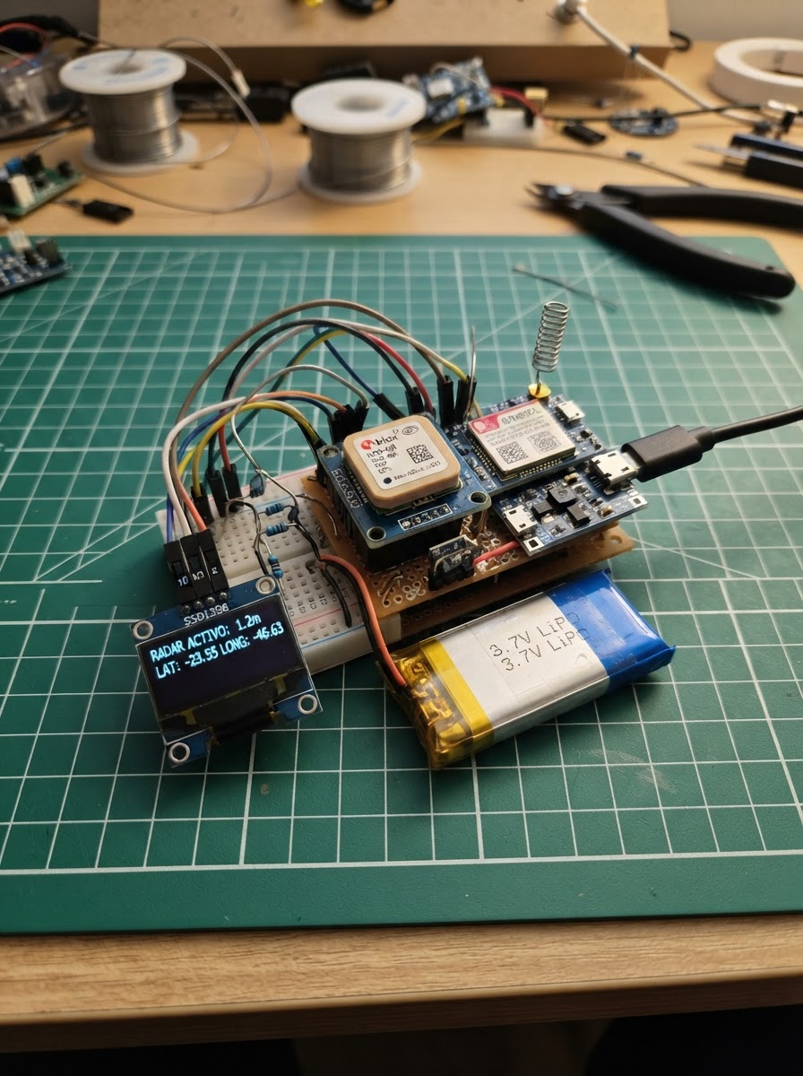
This project builds a portable radar display that tracks GPS positions received via SMS over GSM networks. The ESP32 microcontroller reads the device's own location from a NEO-6M GPS module and displays nearby contacts on a 0.96-inch OLED screen as a radar plot, with range rings showing distance up to 1 kilometer. Contact positions are received through SMS messages via the SIM800L GSM modem and stored in memory for real-time visualization.
The guide provides a complete wiring diagram connecting the GPS module, GSM modem, OLED display, and power management circuit to the ESP32. Assembly steps cover mounting the display panel, configuring the GPS receiver, safely powering the GSM modem with the TP4056 charger and voltage regulator, and establishing GSM signal routing. Included firmware handles GPS parsing, SMS reception and transmission, contact tracking, and radar rendering—everything needed to deploy a working position-sharing tracker.
Wiring diagram

Gather all the parts
Assemble it in 5 steps
1. Monte o painel e a tela
Com o ESP32 desligado, ligue a tela OLED: VCC → 3V3 (power), GND → GND (ground), SDA → GPIO21 (data) e SCL → GPIO22 (clock).
- A tela normalmente mostra o endereço I2C 0x3C; deixe os quatro fios curtos para evitar mau contato.
- Não troque VCC e GND: alimentação invertida pode danificar a tela.
2. Ligue o receptor de posição
Conecte o GPS NEO-6M: VCC → 3V3 (power), GND → GND (ground) e TX → GPIO16 (signal). Deixe o pino RX do GPS sem fio, pois este projeto apenas recebe a posição dele.
- Deixe a antena cerâmica voltada para cima e perto de uma janela ou do lado de fora para encontrar satélites.
- O GPS pode levar alguns minutos para conseguir a primeira posição, principalmente dentro de prédios.
3. Faça a alimentação segura do modem
Ligue a bateria ao TP4056: BAT+ → B+ (power) e BAT- → B- (ground). Ligue OUT+ do TP4056 → VIN do regulador (power), OUT- → GND (ground), e GND do regulador → GND comum (ground). Ajuste o regulador para exatamente 4,0 V antes de ligar o SIM800L; depois ligue VOUT do regulador → VCC do SIM800L (power).
- Use um multímetro para confirmar 4,0 V na saída do regulador antes de conectar o modem.
- O conector USB do TP4056 serve somente para recarregar a bateria.
- Não alimente o SIM800L pelo pino 3V3 do ESP32: uma transmissão GSM pode exigir picos de corrente e fazer o painel reiniciar.
- Uma bateria LiPo ligada ao contrário pode aquecer, danificar o carregador ou causar incêndio.
4. Ligue os sinais do modem GSM
Faça um terra comum: GND do SIM800L → GND do ESP32 (ground). Ligue TXD do SIM800L → GPIO27 do ESP32 (data). Para o caminho no outro sentido, ligue GPIO26 → uma ponta do resistor de 10 kΩ (signal); a outra ponta do resistor de 10 kΩ → RXD do SIM800L (signal). No mesmo ponto RXD, ligue uma ponta do resistor de 22 kΩ; a outra ponta do resistor de 22 kΩ → GND (ground).
- Os dois resistores reduzem os 3,3 V do ESP32 para um valor seguro ao pino RXD do SIM800L.
- Coloque um cartão SIM ativo, sem PIN, e conecte a antena GSM antes de energizar o modem.
- Ligar GPIO26 diretamente ao RXD do SIM800L pode sobrecarregar a entrada de sinal do modem.
- Todos os módulos precisam compartilhar o mesmo GND; sem isso os sinais de dados não têm referência.
5. Energize e publique as posições
Ligue o ESP32 pela porta USB e energize o conjunto GSM pela bateria. Depois de o GPS achar posição, o painel usa a sua posição como centro. Cada rastreador remoto envia um SMS para o número deste SIM com o texto LOC,ID,latitude,longitude, por exemplo LOC,CARRO1,-23.550520,-46.633308.
- O painel aceita até três dispositivos e mostra a distância deles no alcance de 1 km.
- Envie LOC? por SMS ao painel para ele responder com a própria localização.
- Use somente dispositivos e números de telefone para os quais você tem autorização; localização de pessoas sem consentimento pode ser ilegal.
Review all connections
1. Connections between "oled_1" and "ESP32"
2. Connections between "gps_1" and "ESP32"
3. Connections between "gsm_1" and "ESP32"
4. Connections between "battery_1" and "ESP32"
5. Connections between "charger_1" and "ESP32"
6. Connections between "regulator_1" and "ESP32"
7. Connections between "r_top_1" and "ESP32"
8. Connections between "r_bottom_1" and "ESP32"
Deploy the firmware
#include <Arduino.h>
#include <Wire.h>
#include <Adafruit_GFX.h>
#include <Adafruit_SSD1306.h>
#include <TinyGPS++.h>
#include <math.h>


// Hoisted type definitions
struct Contact {
  char id[13];
  float lat;
  float lon;
  uint32_t updatedAt;
  bool valid;
};


// Forward declarations
void sendAT(const char *command);
void drawRadar();
void rememberLocation(const char *id, float lat, float lon);
void sendLocationSms(const char *phone);
void processSms(const char *sender, const char *body);
void processGsmLine(char *line);
void readGsm();

constexpr int OLED_SDA = 21;
constexpr int OLED_SCL = 22;
constexpr int GPS_RX_PIN = 16;
constexpr int GSM_RX_PIN = 27;
constexpr int GSM_TX_PIN = 26;
constexpr uint8_t SCREEN_WIDTH = 128;
constexpr uint8_t SCREEN_HEIGHT = 64;
constexpr float RADAR_RANGE_M = 1000.0f;
constexpr uint32_t POSITION_FRESH_MS = 120000;

Adafruit_SSD1306 display(SCREEN_WIDTH, SCREEN_HEIGHT, &Wire, -1);
TinyGPSPlus gps;
HardwareSerial gpsSerial(1);
HardwareSerial gsmSerial(2);


constexpr uint8_t MAX_CONTACTS = 3;
Contact contacts[MAX_CONTACTS] = {};
float centerLat = 0.0f;
float centerLon = 0.0f;
bool centerValid = false;
char gsmLine[180];
size_t gsmLineLength = 0;
char pendingSender[28] = "";
bool waitingSmsBody = false;

void sendAT(const char *command) {
  gsmSerial.print(command);
  gsmSerial.print("\r");
}

void drawRadar() {
  display.clearDisplay();
  const int cx = 34;
  const int cy = 34;
  display.drawCircle(cx, cy, 10, SSD1306_WHITE);
  display.drawCircle(cx, cy, 20, SSD1306_WHITE);
  display.drawCircle(cx, cy, 29, SSD1306_WHITE);
  display.drawLine(cx - 29, cy, cx + 29, cy, SSD1306_WHITE);
  display.drawLine(cx, cy - 29, cx, cy + 29, SSD1306_WHITE);
  display.fillCircle(cx, cy, 2, SSD1306_WHITE);
  display.setTextSize(1);
  display.setTextColor(SSD1306_WHITE);
  display.setCursor(70, 2);
  display.print("GSM RADAR");
  display.setCursor(70, 12);
  display.print(centerValid ? "GPS OK" : "AGUARDE GPS");
  display.setCursor(70, 22);
  display.print("RAIO 1km");

  uint8_t row = 0;
  for (uint8_t i = 0; i < MAX_CONTACTS; ++i) {
    if (!contacts[i].valid || !centerValid || millis() - contacts[i].updatedAt > POSITION_FRESH_MS) continue;
    const float northM = (contacts[i].lat - centerLat) * 111111.0f;
    const float eastM = (contacts[i].lon - centerLon) * 111111.0f * cosf(centerLat * DEG_TO_RAD);
    const float distanceM = sqrtf(northM * northM + eastM * eastM);
    const float scale = min(distanceM / RADAR_RANGE_M, 1.0f);
    const float divisor = distanceM > 0.1f ? distanceM : 1.0f;
    int x = cx + static_cast<int>((eastM / divisor) * scale * 28.0f);
    int y = cy - static_cast<int>((northM / divisor) * scale * 28.0f);
    display.fillCircle(x, y, 2, SSD1306_WHITE);
    display.setCursor(70, 34 + row * 10);
    display.print(contacts[i].id);
    display.print(' ');
    display.print(static_cast<int>(distanceM));
    display.print('m');
    ++row;
  }
  display.display();
}

void rememberLocation(const char *id, float lat, float lon) {
  int slot = -1;
  for (uint8_t i = 0; i < MAX_CONTACTS; ++i) {
    if (contacts[i].valid && strcmp(contacts[i].id, id) == 0) {
      slot = i;
      break;
    }
    if (!contacts[i].valid && slot < 0) slot = i;
  }
  if (slot < 0) slot = 0;
  strncpy(contacts[slot].id, id, sizeof(contacts[slot].id) - 1);
  contacts[slot].id[sizeof(contacts[slot].id) - 1] = '\0';
  contacts[slot].lat = lat;
  contacts[slot].lon = lon;
  contacts[slot].updatedAt = millis();
  contacts[slot].valid = true;
  drawRadar();
}

void sendLocationSms(const char *phone) {
  if (!gps.location.isValid()) return;
  char body[72];
  snprintf(body, sizeof(body), "LOC,PAINEL,%.6f,%.6f", gps.location.lat(), gps.location.lng());
  gsmSerial.print("AT+CMGS=\"");
  gsmSerial.print(phone);
  gsmSerial.print("\"\r");
  delay(250);
  gsmSerial.print(body);
  gsmSerial.write(26);
}

void processSms(const char *sender, const char *body) {
  char id[13] = {};
  float lat = 0.0f;
  float lon = 0.0f;
  if (sscanf(body, "LOC,%12[^,],%f,%f", id, &lat, &lon) == 3 && lat >= -90.0f && lat <= 90.0f && lon >= -180.0f && lon <= 180.0f) {
    rememberLocation(id, lat, lon);
  } else if (strcmp(body, "LOC?") == 0 && sender[0] != '\0') {
    sendLocationSms(sender);
  }
}

void processGsmLine(char *line) {
  if (strncmp(line, "+CMT:", 5) == 0) {
    const char *first = strchr(line, '\"');
    const char *last = first == nullptr ? nullptr : strchr(first + 1, '\"');
    if (first != nullptr && last != nullptr) {
      size_t len = min(static_cast<size_t>(last - first - 1), sizeof(pendingSender) - 1);
      memcpy(pendingSender, first + 1, len);
      pendingSender[len] = '\0';
    }
    waitingSmsBody = true;
  } else if (waitingSmsBody) {
    processSms(pendingSender, line);
    waitingSmsBody = false;
    pendingSender[0] = '\0';
  }
}

void readGsm() {
  while (gsmSerial.available()) {
    char c = static_cast<char>(gsmSerial.read());
    if (c == '\r') continue;
    if (c == '\n') {
      if (gsmLineLength > 0) {
        gsmLine[gsmLineLength] = '\0';
        processGsmLine(gsmLine);
        gsmLineLength = 0;
      }
    } else if (gsmLineLength < sizeof(gsmLine) - 1) {
      gsmLine[gsmLineLength++] = c;
    }
  }
}

void setup() {
  Serial.begin(115200);
  Wire.begin(OLED_SDA, OLED_SCL);
  display.begin(SSD1306_SWITCHCAPVCC, 0x3C);
  display.clearDisplay();
  display.setTextSize(1);
  display.setTextColor(SSD1306_WHITE);
  display.setCursor(0, 0);
  display.print("Iniciando radar GSM");
  display.display();
  gpsSerial.begin(9600, SERIAL_8N1, GPS_RX_PIN, -1);
  gsmSerial.begin(9600, SERIAL_8N1, GSM_RX_PIN, GSM_TX_PIN);
  delay(800);
  sendAT("AT");
  sendAT("ATE0");
  sendAT("AT+CMGF=1");
  sendAT("AT+CNMI=2,2,0,0,0");
}

void loop() {
  while (gpsSerial.available()) gps.encode(gpsSerial.read());
  if (gps.location.isUpdated()) {
    centerLat = gps.location.lat();
    centerLon = gps.location.lng();
    centerValid = true;
    drawRadar();
  }
  readGsm();
}
Remix this project
Make it yours in one click
Open a full copy of this project in your own Schematik workspace — diagram, code, parts, and assembly steps included. Swap the sensor, add features, or redesign the whole thing with AI. The author's original stays untouched.