Community project
RFID System Login
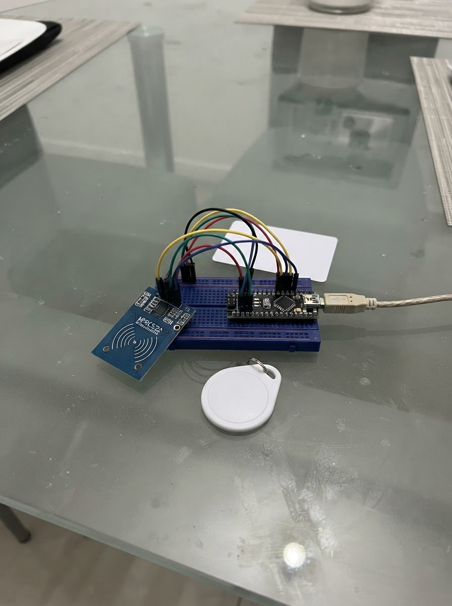
This project turns an ESP32 into an RFID card reader that detects 13.56 MHz tags and fobs, then outputs their unique identifiers over serial. It's useful for building access control systems, attendance trackers, or any application that needs to identify RFID cards. The guide includes a wiring diagram showing how to connect the MFRC522 module to the ESP32's SPI pins, a complete parts list, and ready-to-upload firmware.
Assembly is straightforward: the MFRC522 connects directly to the ESP32's 3.3V power and SPI data lines with just two control pins. The firmware handles card detection and outputs the card UID in hex format with built-in debouncing to prevent duplicate reads. Follow the step-by-step wiring instructions, upload the code, and start scanning cards immediately.
Wiring diagram

Gather all the parts
Assemble it in 5 steps
1. Keep the ESP32 unplugged while wiring
Disconnect the ESP32 USB cable before making connections. USB will later provide both power and the serial link to your computer.
- No separate power supply is needed for this USB-powered reader.
2. Connect RC522 power
Connect RC522 VCC to the ESP32 3V3 pin and RC522 GND to an ESP32 GND pin.
- The RC522 and ESP32 use compatible 3.3 V logic, so no level shifter is used.
- Never connect RC522 VCC to ESP32 5V/VIN.
3. Connect the SPI data wires
Connect RC522 SCK to ESP32 GPIO18, RC522 MISO to GPIO19, and RC522 MOSI to GPIO23.
- Keep these SPI jumpers short and firmly seated for reliable card reads.
4. Connect reader control pins
Connect RC522 SDA (also labeled SS or NSS) to ESP32 GPIO27 and RC522 RST to GPIO26. Leave RC522 IRQ unconnected.
- Despite its SDA label, this RC522 pin is the SPI chip-select pin, not an I2C SDA pin.
5. Power and test
Check the seven connections, then connect the ESP32 to your computer by USB and use Schematik’s Deploy button. The reader reports card IDs at 115200 baud as RFID_UID: followed by the hexadecimal UID.
- Hold a card or fob flat and close to the RC522 antenna.
- Keep the RC522 away from metal surfaces while scanning; metal reduces reading range.
- Do not use card UID alone as the only security check for sensitive access; validate it in your computer-side service.
Review all connections
1. Connections between "rc522_1" and "ESP32"
Deploy the firmware
#include <Arduino.h>
#include <SPI.h>
#include <MFRC522.h>

// ESP32 VSPI: SCK=18, MISO=19, MOSI=23.
// The RC522 is a 3.3 V device and connects directly to this 3.3 V ESP32.
#define RC522_SS_PIN 27
#define RC522_RST_PIN 26


// Forward declarations
String uidToHex(const MFRC522::Uid &uid);

MFRC522 rfid(RC522_SS_PIN, RC522_RST_PIN);

String lastUid = "";
unsigned long lastUidSentAt = 0;
const unsigned long SAME_CARD_COOLDOWN_MS = 1500;

String uidToHex(const MFRC522::Uid &uid) {
  String result;
  for (byte i = 0; i < uid.size; i++) {
    if (uid.uidByte[i] < 0x10) result += '0';
    result += String(uid.uidByte[i], HEX);
  }
  result.toUpperCase();
  return result;
}

void setup() {
  Serial.begin(115200);
  SPI.begin();
  rfid.PCD_Init();
  delay(50);
  Serial.println(F("RFID_LOGIN_READER_READY"));
  Serial.println(F("Present a 13.56 MHz RC522-compatible card or fob."));
}

void loop() {
  if (!rfid.PICC_IsNewCardPresent()) return;
  if (!rfid.PICC_ReadCardSerial()) return;

  const String uid = uidToHex(rfid.uid);
  const unsigned long now = millis();
  if (uid != lastUid || now - lastUidSentAt >= SAME_CARD_COOLDOWN_MS) {
    Serial.print(F("RFID_UID:"));
    Serial.println(uid);
    lastUid = uid;
    lastUidSentAt = now;
  }

  rfid.PICC_HaltA();
  rfid.PCD_StopCrypto1();
  delay(50);
}
Remix this project
Make it yours in one click
Open a full copy of this project in your own Schematik workspace — diagram, code, parts, and assembly steps included. Swap the sensor, add features, or redesign the whole thing with AI. The author's original stays untouched.