Community project
Smart Agarbatti Packaging Dryer
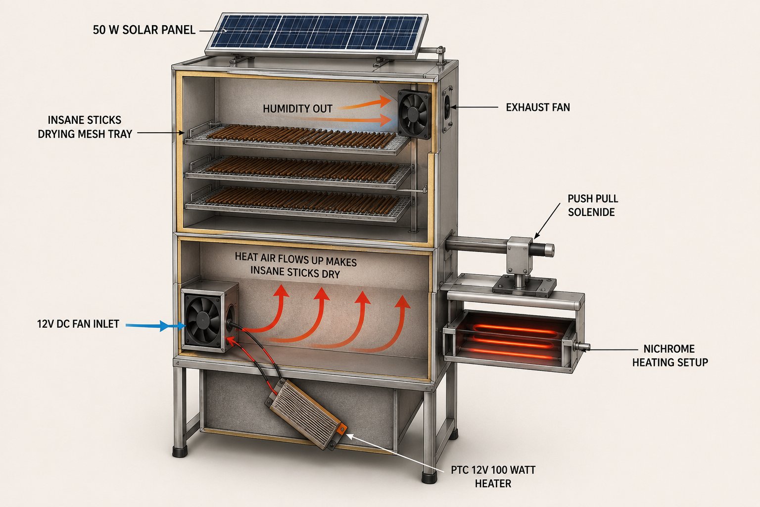
The Smart Agarbatti Packaging Dryer automates the drying and sealing of incense stick packages. It maintains precise temperature and humidity control using a PTC heater, intake and exhaust fans, and a solenoid-driven clamping mechanism, while an IR line sensor detects package position and a nichrome sealer fuses the pouch closed.
This guide provides a complete wiring diagram, parts list, and ESP32 firmware with PID temperature control. Assembly steps cover mounting the heating and mechanical components, connecting low-voltage sensors via I2C, wiring the ESP32 control outputs to MOSFET modules, and safely testing the 12 V power distribution before operation.
Wiring diagram

Gather all the parts
Assemble it in 5 steps
1. Mount the hot and moving parts
Fix the PTC heater, intake fan, and exhaust fan to a non-flammable drying chamber. Keep the SHT31 sensor away from the direct heater stream so it measures the chamber air rather than the heater surface. Mount the nichrome sealing element behind a heat-resistant guard so fingers and pouch contents cannot touch it.
- Leave a clear air path from the intake fan, past the agarbatti, to the exhaust fan.
- Use high-temperature wire and heat-resistant terminals around the heater and sealing element.
- The heater and nichrome wire can burn skin or start a fire; do not use a breadboard, loose jumper wires, or flammable mounting material for these parts.
2. Wire the low-voltage sensors
With all power unplugged, connect SHT31 VCC to ESP32 3V3 (power), SHT31 GND to ESP32 GND (ground), SHT31 SDA to GPIO21 (data), and SHT31 SCL to GPIO22 (data). Connect the TCRT5000 sensor VCC to ESP32 3V3 (power), GND to ESP32 GND (ground), and DO to GPIO32 (pouch signal). Turn its small adjustment screw until it changes state only when a pouch is in the sealing position.
- Powering the IR sensor from 3.3 V ensures its output cannot put a harmful 5 V signal into the ESP32.
- Keep the sensor face clean and shield it from strong sunlight or reflections from the hot sealer.
- Do not connect a 5 V sensor output directly to an ESP32 pin; the ESP32 pins use 3.3 V signals.
3. Connect the ESP32 control wires
Connect heater_switch_1 IN to GPIO25 (heater control), intake_fan_switch_1 IN to GPIO26 (intake fan control), exhaust_fan_switch_1 IN to GPIO27 (exhaust fan control), solenoid_switch_1 IN to GPIO33 (clamp control), and sealer_switch_1 IN to GPIO14 (sealer control). Connect buzzer_1 SIGNAL to GPIO13 (finished-cycle sound) and buzzer_1 GND to ESP32 GND (ground). Connect the GND terminal of every MOSFET switch module to ESP32 GND (common reference).
- Label each control wire before connecting the load side; this makes a later safety check much easier.
- GPIO13 is used for the buzzer so the ESP32 avoids the boot-sensitive GPIO12 pin.
- Never connect a heater, fan, solenoid, or nichrome wire directly to an ESP32 pin; each load must go through its MOSFET switch module.
4. Wire the fused 12 V load side
Install a fuse close to supply_12v_1 positive output, then connect its +12V to each MOSFET module VLOAD+ (load power). Connect heater_switch_1 OUT- to ptc_heater_1 HEATER- (switched heater return) and the heater positive lead to +12V (power). Connect each fan positive lead to +12V (power) and its negative lead to its matching switch OUT- (switched return). Connect clamp_solenoid_1 SOL+ to +12V (power) and SOL- to solenoid_switch_1 OUT- (switched return). Connect nichrome_sealer_1 SEAL+ to +12V (power) and SEAL- to sealer_switch_1 OUT- (switched return). Connect supply_12v_1 GND to ESP32 GND (common ground).
- Use a separate branch fuse for the heater and sealing element once their labelled current is known; choose wire thickness and fuse ratings for the real current.
- Use a solenoid switch module that already includes a flyback diode, or fit a diode across the solenoid coil: stripe to +12 V and the other end to the switched negative lead.
- A reversed diode or an undersized MOSFET can fail dangerously. The 12 V supply must be rated for the heater, sealer, fans, and solenoid current, not just for the ESP32.
5. Do a cold safety test
Before fitting agarbatti or a pouch, unplug the 12 V supply and check that every load wire is firmly clamped and cannot touch another terminal. Plug in the ESP32 by USB first, then connect the 12 V supply. Confirm the sensor readings appear in the Deploy output and confirm each load is off at startup. Test the pouch sensor with a scrap pouch, watching from a safe distance while the clamp and seal cycle operate.
- Start with a shorter sealing pulse in firmware if the pouch material is unknown, then increase only after test seals.
- Keep a suitable fire extinguisher nearby during all heater and sealer tests.
- Do not leave the system unattended while the heater or sealing element is powered. Disconnect 12 V immediately if a wire gets hot, insulation smells, or a load remains on unexpectedly.
Review all connections
1. Connections between "sht31_1" and "ESP32"
2. Connections between "ir_pouch_sensor_1" and "ESP32"
3. Connections between "heater_switch_1" and "ESP32"
4. Connections between "intake_fan_switch_1" and "ESP32"
5. Connections between "exhaust_fan_switch_1" and "ESP32"
6. Connections between "solenoid_switch_1" and "ESP32"
7. Connections between "sealer_switch_1" and "ESP32"
8. Connections between "buzzer_1" and "ESP32"
9. Connections between "supply_12v_1" and "ESP32"
Deploy the firmware
#include <Arduino.h>
#include <Wire.h>
#include <Adafruit_SHT31.h>
#include <PID_v1.h>

// ESP32 control pins, matched to the wiring diagram.

// Hoisted type definitions
enum class PackageState { WAITING, CLAMPING, SEALING, COOLING, BEEPING, WAIT_FOR_CLEAR };


// Forward declarations
void setHeater(uint8_t duty);
void allPackagingOutputsOff();
void enterPackagingState(PackageState nextState, uint32_t now);
void readAndControlDryer(uint32_t now);
void runPackagingCycle(uint32_t now);

constexpr uint8_t HEATER_PIN = 25;
constexpr uint8_t INTAKE_FAN_PIN = 26;
constexpr uint8_t EXHAUST_FAN_PIN = 27;
constexpr uint8_t IR_SENSOR_PIN = 32;
constexpr uint8_t SOLENOID_PIN = 33;
constexpr uint8_t SEALER_PIN = 14;
constexpr uint8_t BUZZER_PIN = 13;
constexpr uint8_t SHT31_SDA_PIN = 21;
constexpr uint8_t SHT31_SCL_PIN = 22;

constexpr float TARGET_TEMP_C = 38.0F;
constexpr float MAX_SAFE_TEMP_C = 50.0F;
constexpr float HUMIDITY_LIMIT_PERCENT = 80.0F;
constexpr uint32_t SENSOR_INTERVAL_MS = 1000;
constexpr uint32_t PURGE_DURATION_MS = 30000;
constexpr uint32_t SOLENOID_SETTLE_MS = 100;
constexpr uint32_t SEAL_PULSE_MS = 1200;
constexpr uint32_t COOLING_HOLD_MS = 1500;
constexpr uint32_t BUZZER_MS = 300;
constexpr uint32_t POUCH_CLEAR_MS = 500;
constexpr uint8_t HEATER_PWM_CHANNEL = 0;
constexpr uint32_t HEATER_PWM_HZ = 5000;
constexpr uint8_t HEATER_PWM_BITS = 8;

Adafruit_SHT31 sht31;
double setpoint = TARGET_TEMP_C;
double inputTemp = 0.0;
double heaterOutput = 0.0;
PID heaterPID(&inputTemp, &heaterOutput, &setpoint, 10.0, 0.5, 1.0, DIRECT);


PackageState packageState = PackageState::WAITING;

bool sensorReady = false;
bool isPurging = false;
bool heaterSafetyLockout = false;
uint32_t lastSensorReadMs = 0;
uint32_t purgeStartedMs = 0;
uint32_t packageStateStartedMs = 0;

void setHeater(uint8_t duty) {
  ledcWrite(HEATER_PWM_CHANNEL, duty);
}

void allPackagingOutputsOff() {
  digitalWrite(SOLENOID_PIN, LOW);
  digitalWrite(SEALER_PIN, LOW);
  digitalWrite(BUZZER_PIN, LOW);
}

void enterPackagingState(PackageState nextState, uint32_t now) {
  packageState = nextState;
  packageStateStartedMs = now;
}

void readAndControlDryer(uint32_t now) {
  if (now - lastSensorReadMs < SENSOR_INTERVAL_MS) return;
  lastSensorReadMs = now;

  const float temperature = sht31.readTemperature();
  const float humidity = sht31.readHumidity();
  if (isnan(temperature) || isnan(humidity)) {
    Serial.println("SHT31 reading failed; heater switched off.");
    setHeater(0);
    digitalWrite(INTAKE_FAN_PIN, LOW);
    digitalWrite(EXHAUST_FAN_PIN, HIGH);
    return;
  }

  Serial.printf("Dryer: %.1f C, %.1f %%RH\n", temperature, humidity);
  inputTemp = temperature;

  if (temperature >= MAX_SAFE_TEMP_C) {
    if (!heaterSafetyLockout) Serial.println("Temperature safety cutoff active.");
    heaterSafetyLockout = true;
  } else if (heaterSafetyLockout && temperature < TARGET_TEMP_C) {
    heaterSafetyLockout = false;
    Serial.println("Temperature returned to the normal range.");
  }

  if (heaterSafetyLockout) {
    isPurging = false;
    setHeater(0);
    digitalWrite(INTAKE_FAN_PIN, LOW);
    digitalWrite(EXHAUST_FAN_PIN, HIGH);
    return;
  }

  if (!isPurging && humidity >= HUMIDITY_LIMIT_PERCENT) {
    isPurging = true;
    purgeStartedMs = now;
    Serial.println("High humidity: starting 30 second purge.");
  }

  if (isPurging) {
    setHeater(0);
    digitalWrite(INTAKE_FAN_PIN, LOW);
    digitalWrite(EXHAUST_FAN_PIN, HIGH);
    if (now - purgeStartedMs >= PURGE_DURATION_MS) {
      isPurging = false;
      digitalWrite(EXHAUST_FAN_PIN, LOW);
      Serial.println("Purge complete; resuming drying.");
    }
    return;
  }

  digitalWrite(INTAKE_FAN_PIN, HIGH);
  digitalWrite(EXHAUST_FAN_PIN, LOW);
  heaterPID.Compute();
  setHeater(static_cast<uint8_t>(heaterOutput));
}

void runPackagingCycle(uint32_t now) {
  const bool pouchPresent = digitalRead(IR_SENSOR_PIN) == LOW;

  switch (packageState) {
    case PackageState::WAITING:
      if (pouchPresent) {
        Serial.println("Pouch detected: clamping.");
        digitalWrite(SOLENOID_PIN, HIGH);
        enterPackagingState(PackageState::CLAMPING, now);
      }
      break;

    case PackageState::CLAMPING:
      if (now - packageStateStartedMs >= SOLENOID_SETTLE_MS) {
        Serial.println("Sealing pouch.");
        digitalWrite(SEALER_PIN, HIGH);
        enterPackagingState(PackageState::SEALING, now);
      }
      break;

    case PackageState::SEALING:
      if (now - packageStateStartedMs >= SEAL_PULSE_MS) {
        digitalWrite(SEALER_PIN, LOW);
        enterPackagingState(PackageState::COOLING, now);
      }
      break;

    case PackageState::COOLING:
      if (now - packageStateStartedMs >= COOLING_HOLD_MS) {
        digitalWrite(SOLENOID_PIN, LOW);
        digitalWrite(BUZZER_PIN, HIGH);
        enterPackagingState(PackageState::BEEPING, now);
      }
      break;

    case PackageState::BEEPING:
      if (now - packageStateStartedMs >= BUZZER_MS) {
        digitalWrite(BUZZER_PIN, LOW);
        Serial.println("Sealed pouch ready.");
        enterPackagingState(PackageState::WAIT_FOR_CLEAR, now);
      }
      break;

    case PackageState::WAIT_FOR_CLEAR:
      if (!pouchPresent && now - packageStateStartedMs >= POUCH_CLEAR_MS) {
        enterPackagingState(PackageState::WAITING, now);
      }
      break;
  }
}

void setup() {
  Serial.begin(115200);
  pinMode(INTAKE_FAN_PIN, OUTPUT);
  pinMode(EXHAUST_FAN_PIN, OUTPUT);
  pinMode(SOLENOID_PIN, OUTPUT);
  pinMode(SEALER_PIN, OUTPUT);
  pinMode(BUZZER_PIN, OUTPUT);
  pinMode(IR_SENSOR_PIN, INPUT_PULLUP);

  digitalWrite(INTAKE_FAN_PIN, LOW);
  digitalWrite(EXHAUST_FAN_PIN, LOW);
  allPackagingOutputsOff();

  ledcSetup(HEATER_PWM_CHANNEL, HEATER_PWM_HZ, HEATER_PWM_BITS);
  ledcAttachPin(HEATER_PIN, HEATER_PWM_CHANNEL);
  setHeater(0);

  Wire.begin(SHT31_SDA_PIN, SHT31_SCL_PIN);
  sensorReady = sht31.begin(0x44);
  if (!sensorReady) {
    Serial.println("SHT31 not found; heater remains off until fixed.");
  }

  heaterPID.SetOutputLimits(0, 255);
  heaterPID.SetSampleTime(SENSOR_INTERVAL_MS);
  heaterPID.SetMode(AUTOMATIC);
  Serial.println("Smart agarbatti dryer and sealer started.");
}

void loop() {
  const uint32_t now = millis();
  if (sensorReady) readAndControlDryer(now);
  else setHeater(0);
  runPackagingCycle(now);
}
Remix this project
Make it yours in one click
Open a full copy of this project in your own Schematik workspace — diagram, code, parts, and assembly steps included. Swap the sensor, add features, or redesign the whole thing with AI. The author's original stays untouched.