Community project
Smart Child Health Box
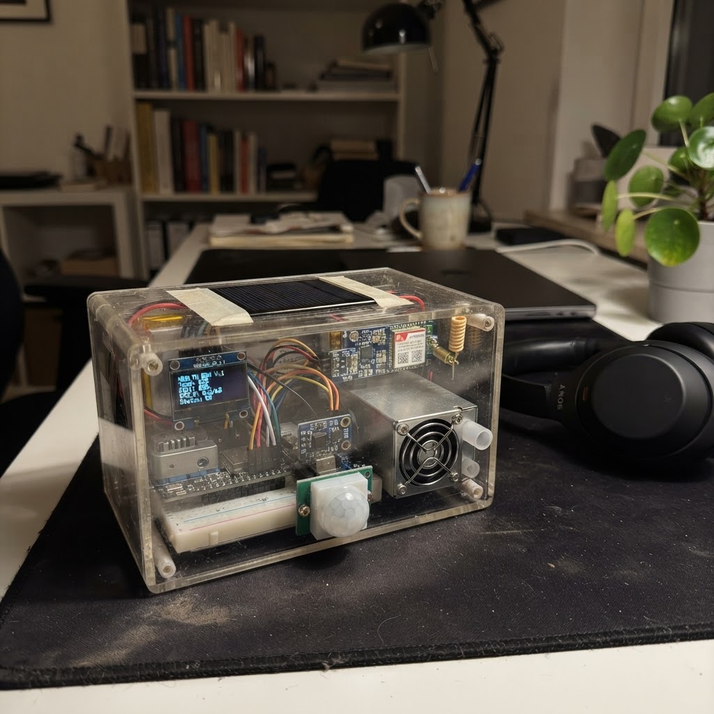
The Smart Child Health Box is an environmental monitoring station designed to track air quality, weather, and light conditions in spaces where children learn and play. Built around an ESP32 microcontroller, it combines CO2 and particulate matter sensors with temperature, humidity, light, and UV measurement to provide comprehensive indoor and outdoor environmental data.
This guide includes a complete parts list, wiring diagram, PCB layout, and step-by-step assembly instructions for building the device into a wall-mounted enclosure. The included firmware reads all sensors via I2C and serial interfaces, displays real-time measurements on an OLED screen, and supports long-range data transmission via LoRa or LTE connectivity. Solar charging with battery backup ensures continuous operation in any location.
Wiring diagram

Gather all the parts
Assemble it in 4 steps
1. Prepare the enclosure and wall plate
Use a 10 in high × 4 in wide × 6 in deep IP65 ABS/polycarbonate enclosure. Fit the sliding backplate rails, two keyhole wall slots, and a bottom security-screw hole. Install filtered downward-facing lower louvers; keep the sensor chamber thermally separated from the RF/power area.
- Use a closed-cell gasket and stainless mounting screws.
- Put a drip loop in the solar cable before the upper-side DC entry.
- Do not place the solar panel on the enclosure; mount it outside on its own tilt bracket.
- Do not obstruct PM sensor airflow or cover the cellular/GNSS/LoRa antenna areas.
2. Install the single vertical PCB and electronics zones
Mount one vertical PCB on standoffs: radios and antenna connectors at the top, ESP32/power/display connector in the middle, and SCD41/PMS5003 at the bottom directly above the filtered vents. Fix the protected 18650 holder close to the back wall/lower board.
- Keep the PM optical inlet/outlet aligned to separate lower vent paths.
- Keep cellular supply traces short and use the modem manufacturer’s bulk capacitors at VCC.
- Use only a protected 18650 Li-ion cell of the specified type; observe holder polarity.
- The SIM7600 needs a 4.0V rail able to tolerate 2A transmit pulses.
3. Connect front components and outdoor interfaces
Mount the OLED, UV window, light aperture, PIR lens and alert light pipes in the front cover. Connect the tipping-bucket rain gauge through a weatherproof cable gland. Connect the detached panel to the recessed locking DC input and attach the approved regional LoRa, LTE and GNSS antennas to top SMA connectors.
- Use a UV-transparent window only over the UV sensor.
- Use a rain gauge with a dry-contact output and keep its cable away from antenna cables.
- Disconnect solar and remove the battery before servicing.
- Use the legal LoRa frequency and certified cellular antenna/SIM for the deployment country.
4. Mount and commission
Screw the plate securely to brick, concrete or wood, slide the unit down until seated, then fit the bottom security screw. Insert the battery, connect the solar panel, and use Schematik’s Deploy button to flash the supplied firmware. Confirm the display changes after each five-second sensor sampling cycle.
- Orient the external panel toward maximum daily sunlight and adjust its tilt seasonally.
- Record rain-gauge millimetres-per-tip locally; the sample firmware currently reports raw tip count.
- The unit is weather-resistant only when the cover gasket, cable glands and unused ports are sealed.
- Do not operate a cellular modem without its antenna connected.
Review all connections
1. Connections between "solar_1" and "ESP32"
2. Connections between "battery_1" and "ESP32"
3. Connections between "charger_1" and "ESP32"
4. Connections between "reg_3v3_1" and "ESP32"
5. Connections between "reg_4v0_1" and "ESP32"
6. Connections between "scd41_1" and "ESP32"
7. Connections between "pm25_1" and "ESP32"
8. Connections between "uv_1" and "ESP32"
9. Connections between "lux_1" and "ESP32"
10. Connections between "oled_1" and "ESP32"
11. Connections between "pir_1" and "ESP32"
12. Connections between "rain_1" and "ESP32"
13. Connections between "lora_1" and "ESP32"
14. Connections between "lte_gps_1" and "ESP32"
Deploy the firmware
#include <Arduino.h>
#include <Wire.h>
#include <Adafruit_GFX.h>
#include <Adafruit_SSD1306.h>
#include <SensirionI2cScd4x.h>
#include <Adafruit_PM25AQI.h>
#include <BH1750.h>
#include <Adafruit_VEML6075.h>

#define I2C_SDA 21
#define I2C_SCL 22
#define PM_RX_PIN 16
#define PIR_PIN 25
#define RAIN_PIN 32
#define OLED_ADDR 0x3C


// Forward declarations
void sampleSensors();
void drawScreen();

Adafruit_SSD1306 display(128, 64, &Wire, -1);
SensirionI2cScd4x scd4x;
Adafruit_PM25AQI pm;
HardwareSerial pmSerial(2);
BH1750 lightMeter;
Adafruit_VEML6075 uv;

uint16_t co2ppm = 0;
float tempC = NAN, humidity = NAN, lux = NAN, uvi = NAN;
uint16_t pm25 = 0;
uint32_t rainTips = 0;
bool lastRain = HIGH;
uint32_t lastSample = 0;
uint32_t lastScreen = 0;

void sampleSensors() {
  uint16_t error;
  char errorMessage[64];
  error = scd4x.readMeasurement(co2ppm, tempC, humidity);
  if (error && error != 0x0000) { co2ppm = 0; }
  PM25_AQI_Data data;
  if (pm.read(&data)) pm25 = data.pm25_env;
  lux = lightMeter.readLightLevel();
  uvi = uv.readUVI();
}

void drawScreen() {
  display.clearDisplay();
  display.setTextColor(SSD1306_WHITE);
  display.setTextSize(1);
  display.setCursor(0, 0); display.println("SCHEB CHILD HEALTH");
  display.printf("T: %.1f C  RH: %.0f%%\n", tempC, humidity);
  display.printf("PM2.5: %u ug/m3\n", pm25);
  display.printf("CO2: %u ppm\n", co2ppm);
  display.printf("UV: %.1f  Lux: %.0f\n", uvi, lux);
  display.printf("Rain: %lu tips\n", (unsigned long)rainTips);
  display.printf("Occupancy: %s", digitalRead(PIR_PIN) ? "MOTION" : "clear");
  display.display();
}

void setup() {
  pinMode(PIR_PIN, INPUT);
  pinMode(RAIN_PIN, INPUT_PULLUP);
  Wire.begin(I2C_SDA, I2C_SCL);
  display.begin(SSD1306_SWITCHCAPVCC, OLED_ADDR);
  display.clearDisplay(); display.display();
  scd4x.begin(Wire);
  scd4x.stopPeriodicMeasurement();
  scd4x.startPeriodicMeasurement();
  lightMeter.begin(BH1750::CONTINUOUS_HIGH_RES_MODE, 0x23, &Wire);
  uv.begin();
  pmSerial.begin(9600, SERIAL_8N1, PM_RX_PIN, -1);
  pm.begin_UART(&pmSerial);
}

void loop() {
  bool rainNow = digitalRead(RAIN_PIN);
  if (lastRain == HIGH && rainNow == LOW) rainTips++;
  lastRain = rainNow;
  uint32_t now = millis();
  if (now - lastSample >= 5000) { lastSample = now; sampleSensors(); }
  if (now - lastScreen >= 1000) { lastScreen = now; drawScreen(); }
}
Remix this project
Make it yours in one click
Open a full copy of this project in your own Schematik workspace — diagram, code, parts, and assembly steps included. Swap the sensor, add features, or redesign the whole thing with AI. The author's original stays untouched.