Community project
SMS OTP Smart Locker
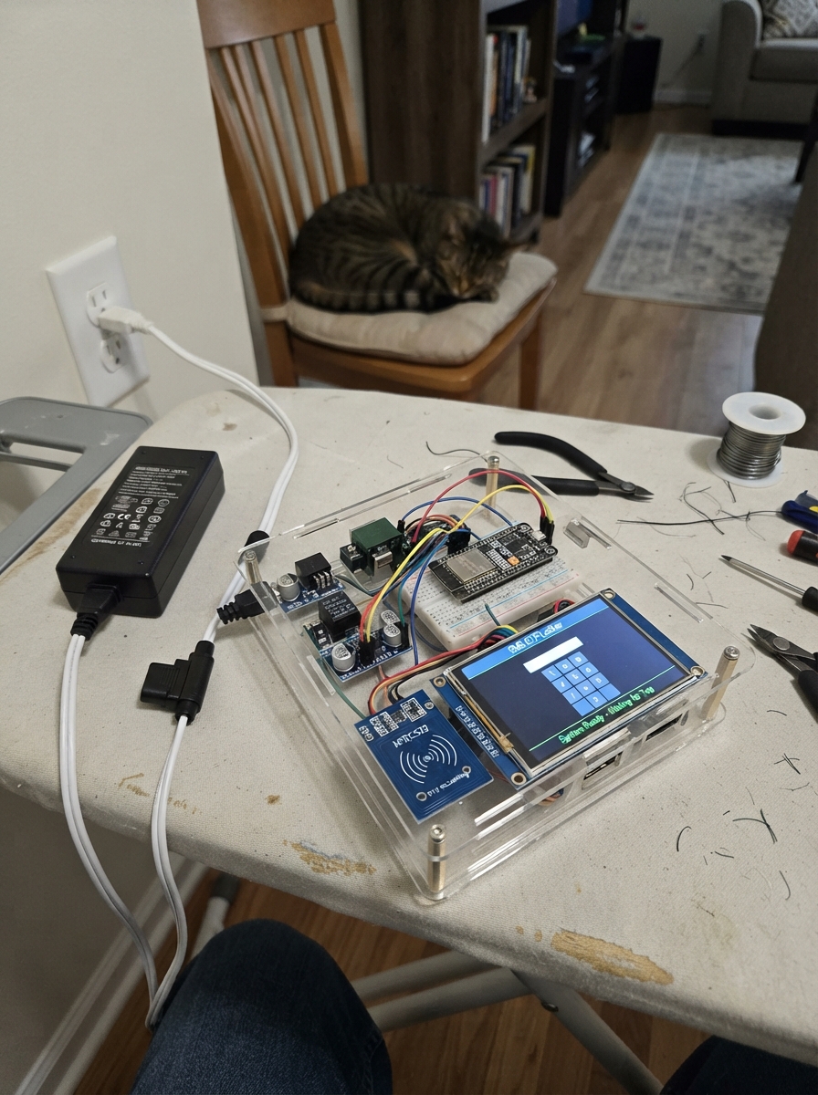
The SMS OTP Smart Locker is a secure item storage system that uses RFID authentication, SMS-based one-time passwords, and ultrasonic level sensing to manage three independent lockable compartments. Built around an ESP32 microcontroller with a 4G modem, touchscreen interface, and networked relay control, it provides a complete audit trail of deposits and pickups stored on an SD card.
This guide covers the full assembly and commissioning of the locker cabinet, including power distribution across three isolated buck converters, wiring the I2C port expander for relay and sensor control, integrating the RFID reader and capacitive touchscreen, and uploading the firmware that orchestrates OTP generation, SMS delivery, and compartment locking. You'll learn how to calibrate the ultrasonic sensors for your cabinet geometry, configure the 4G modem for SMS, and safely bring up each subsystem before accepting items.
Wiring diagram

Gather all the parts
Assemble it in 17 steps
1. Build the cabinet
Use 12mm plywood: outside 600mm wide × 450mm deep × 1350mm high. Make the left locker column 400mm clear width and right service bay 164mm clear width, separated by a 12mm partition. Fit three compartments with approximately 388mm clear height and 414mm usable depth. Their floors are 72, 472 and 872mm above the base. Confirm actual clearances before cutting. Use glued and screwed joints, rounded edges, three individually hinged doors and a removable, keyed rear service cover. Label Locker 1 at the top, 2 middle and 3 bottom.
- Wide plinth and anti-tip restraint are required before use; keep children from climbing. Plywood is for a supervised prototype, not a fire-rated installation.
2. Prepare the front service panel
Mount the portrait touchscreen in the right-hand bay with its center about 1080mm above the floor. Its PCB is approximately 56.34 × 98mm; make the aperture from the actual bezel, not this outline. Mount the RFID reader below it behind a thin nonmetal panel. Fit a red and green LED next to each numbered locker door. Keep the front service panel secured against public access.
3. Fit the three locks
Select 12V, 0.6A maximum, continuous-duty, fail-secure spring-latch bolt locks with power-to-release, push-to-latch action and a manual service release. Ordinary sliding solenoids that cannot latch when pushed shut are not equivalent. Bolt each lock to a reinforced frame and its matching strike to the door. Recess moving parts and check alignment by hand before applying power.
- A reed switch proves only that the door is near closed, not that the bolt is engaged. No motor or door closer is included. Never use this system for life-safety doors.
4. Fit the door sensors
Place each reed switch on the fixed frame near the free edge, with its magnet on the matching door. Choose the contact that closes when the magnet is near. Route switch wires along the frame, not across hinge gaps. Reed A connects to expander P9, P10 or P11 respectively; B goes to common ground. Each listed 10k resistor pulls its signal up to 3.3V.
5. Mount and check the ultrasonic sensors
Mount one HC-SR04P near each ceiling, aimed down into a clearly marked item zone. Adjust mounting so the empty distance is approximately 37cm. Keep the acoustic path away from walls and locks. Use only the 3.3V-compatible P version. Echo outputs go to GPIO34, GPIO35 and GPIO36; triggers go to expander P12, P13 and P14. Power these sensors from the separate peripheral 3.3V rail.
- Plain 5V HC-SR04 sensors cannot be substituted without echo voltage dividers and verified trigger translation. Thin papers, soft food packaging and objects outside the beam may not be detected.
6. Lay out the service bay
Fasten electronics to insulated standoffs on a removable backplate. Place controller, expander and SPI modules near the touchscreen; place converters and fuses lower down and relays at the lock cable exits. Keep SPI wiring ideally below 15cm and I2C below 20cm; use twisted signal/ground pairs where practical. Keep 12V lock wiring in a separate duct. Provide ventilation and labeled plug connectors for each compartment.
7. Install protected DC power
Keep mains voltage outside the cabinet: use an enclosed, certified 12V 5A adapter. Run adapter positive through the 5A main fuse, then distribute 12V to the three converters and the three 1A time-delay lock branch fuses. Use insulated screw terminals and strain relief, approximately 18 AWG for the main feed and 22 AWG for each lock branch. Grounds meet at a star distribution point.
- Do not install a bare mains power supply in a student-built cabinet. Disconnect power before wiring. Fuse ratings protect the selected wire, not just the load.
8. Set converter voltages before connection
With loads disconnected, adjust logic converter to 5.0V, dedicated cellular converter to 5.0V and peripheral converter to 3.3V using a meter. The logic and cellular converters must each supply at least 3A continuously with adequate cooling. The peripheral converter is rated at least 1A. All converter grounds are common, but their positive outputs are separate. Fit the 470uF capacitor across logic 5V and 1000uF across cellular 5V near their loads; observe marked polarity.
- Do not join the separate peripheral 3.3V output to the ESP32 3V3 pin. Do not connect either 5V branch to 3.3V modules.
9. Power the controller safely
The logic 5V branch feeds the ESP32 VIN/5V pin through the removable jumper; grounds are common. Remove this jumper whenever USB is connected for Deploy or maintenance. Power the other peripherals from their designated converters. Replace the jumper only after USB is disconnected.
- Never join USB 5V and external VIN on an unverified DevKit board; their protection differs between manufacturers.
10. Wire the expander
Use a DIP-28 MCP23017, with VDD pin 9 at peripheral 3.3V, VSS pin 10 to ground, SDA pin 13 to GPIO21 (data), SCL pin 12 to GPIO22 (clock), RESET pin 18 to 3.3V, and address pins 15,16,17 to ground. Fit the 100nF capacitor at VDD/VSS and the two 4.7k I2C pull-ups to peripheral 3.3V. P0–P7 mean GPA0–GPA7 (chip pins 21–28); P8–P15 mean GPB0–GPB7 (chip pins 1–8). P15 is unused.
11. Buffer the relay inputs
ULN2003A DIP16: input pins 1,2,3 receive P0,P1,P2; corresponding output pins 16,15,14 go to relay IN1,IN2,IN3. Pin8 goes to ground; pin9 COM to logic 5V. Fit the three 10k pull-downs from these inputs to ground so relays default off. Leave unused inputs/outputs unconnected. The relay module gets logic 5V and ground. Select active-low inputs drawing no more than 5mA with guaranteed LOW recognition at 0.9V or less. Test each channel without locks first.
- The ULN buffer keeps relay 5V off ESP32 and expander pins. This common-ground circuit is not galvanically isolated even if the relay board has optocouplers.
12. Connect each lock branch
For each locker: fused 12V goes to that relay COM, relay NO goes to lock positive, and lock negative goes to common ground. Relay NC is unused. Fit the matching 1N5408 diode directly across the lock: banded cathode at lock positive, anode at lock negative. Contacts must be rated at least 3A at 30VDC.
- Reversing a flyback diode shorts the supply when the relay closes. Do not route lock current through breadboard contacts or microcontroller pins.
13. Connect the LEDs and sounder
P3/P4 drive Locker1 red/green, P5/P6 Locker2 and P7/P8 Locker3. Every LED has its own 1k series resistor into the anode; cathode goes to ground. GPIO13 drives the passive piezo through its 100 ohm resistor; piezo negative goes to ground. Use the specified low-current piezo, not a magnetic speaker.
14. Wire the shared SPI devices
GPIO18 is clock, GPIO23 sends data and GPIO19 receives data for touch, RFID and MicroSD. Display CS goes to GPIO27, DC to GPIO26, RESET to GPIO4; display LED to peripheral 3.3V. Display power is logic 5V, logic is 3.3V. Touch CS goes to GPIO25; RC522 SDA/CS to GPIO33 and RST to GPIO14; MicroSD CS to GPIO32. Add each listed 10k CS pull-up to peripheral 3.3V. Leave LCD SDO/MISO disconnected; connect only touch T_DO to the receive bus. Touch IRQ is unused. RC522 and MicroSD use peripheral 3.3V. Add the MicroSD 100nF bypass capacitor.
- Use a native 3.3V MicroSD breakout without a non-tristating 5V level shifter. Do not use a 5V Uno display shield or a Raspberry Pi screen instead of the specified module.
15. Install cellular hardware
Fit an SMS-enabled SIM and compatible MAIN LTE antenna to the SIM7600G-H HAT before power-up. Select its onboard 3.3V UART setting and auto-start configuration. Feed its 5V input from the dedicated cellular branch, not the ESP32. HAT TXD goes to GPIO16 (ESP32 receives); HAT RXD to GPIO17 (ESP32 sends). Grounds are common. Leave PWR, flight mode and USB disconnected in normal use.
- This wiring is for the regulated, UART-level-shifted HAT, not a bare SIM7600 module. Confirm local LTE bands and SMS service; LTE data support alone does not guarantee SMS.
16. Prepare local storage and cards
Insert a FAT32-formatted 16GB MicroSD into the separate SD module. Use registered ISO14443A 13.56MHz cards. An administrator creates cards.csv on the card with one numeric student ID and uppercase UID hex per line, separated by a comma. No header is required. Keep the service bay locked so the whitelist and wiring cannot be changed by users.
- UID-based RFID cards can be copied. This prototype is not a secure commercial credential system.
17. Commission mechanics before real deposits
Test each door repeatedly with empty compartments, then a rigid test package at least 6cm tall in the marked beam zone. Verify closed-door switch alignment, latch engagement, safe manual override, cable clearance and no accessible pinch point. Disconnect and restore power while a test session is active; that locker must show Service needed instead of being advertised as free. Keep personal items out until all tests pass.
- No-echo is a fault, not proof that a locker is empty. The five-second timer never physically closes a door. Refrigeration, fire protection and tamper detection are not included.
Review all connections
1. Connections between "psu" and "ESP32"
2. Connections between "fmain" and "ESP32"
3. Connections between "logic" and "ESP32"
4. Connections between "cellpower" and "ESP32"
5. Connections between "lowpower" and "ESP32"
6. Connections between "isolate" and "ESP32"
7. Connections between "screen" and "ESP32"
8. Connections between "rfid" and "ESP32"
9. Connections between "sd" and "ESP32"
10. Connections between "sim" and "ESP32"
11. Connections between "io" and "ESP32"
12. Connections between "pullsda" and "ESP32"
13. Connections between "pullscl" and "ESP32"
14. Connections between "driver" and "ESP32"
15. Connections between "relay" and "ESP32"
16. Connections between "sonar1" and "ESP32"
17. Connections between "reed1" and "ESP32"
18. Connections between "reedpull1" and "ESP32"
19. Connections between "red1" and "ESP32"
20. Connections between "rred1" and "ESP32"
21. Connections between "green1" and "ESP32"
22. Connections between "rgreen1" and "ESP32"
23. Connections between "safe1" and "ESP32"
24. Connections between "fuse1" and "ESP32"
25. Connections between "lock1" and "ESP32"
26. Connections between "fly1" and "ESP32"
27. Connections between "sonar2" and "ESP32"
28. Connections between "reed2" and "ESP32"
29. Connections between "reedpull2" and "ESP32"
30. Connections between "red2" and "ESP32"
31. Connections between "rred2" and "ESP32"
32. Connections between "green2" and "ESP32"
33. Connections between "rgreen2" and "ESP32"
34. Connections between "safe2" and "ESP32"
35. Connections between "fuse2" and "ESP32"
36. Connections between "lock2" and "ESP32"
37. Connections between "fly2" and "ESP32"
38. Connections between "sonar3" and "ESP32"
39. Connections between "reed3" and "ESP32"
40. Connections between "reedpull3" and "ESP32"
41. Connections between "red3" and "ESP32"
42. Connections between "rred3" and "ESP32"
43. Connections between "green3" and "ESP32"
44. Connections between "rgreen3" and "ESP32"
45. Connections between "safe3" and "ESP32"
46. Connections between "fuse3" and "ESP32"
47. Connections between "lock3" and "ESP32"
48. Connections between "fly3" and "ESP32"
49. Connections between "rbuzz" and "ESP32"
50. Connections between "buzzer" and "ESP32"
51. Connections between "cmodem" and "ESP32"
52. Connections between "clogic" and "ESP32"
53. Connections between "cio" and "ESP32"
54. Connections between "csd" and "ESP32"
55. Connections between "cstft" and "ESP32"
56. Connections between "cstouch" and "ESP32"
57. Connections between "csrfid" and "ESP32"
58. Connections between "cssd" and "ESP32"
Deploy the firmware
#include <Arduino.h>
#include <Wire.h>
#include <SPI.h>
#include <SD.h>
#include <Preferences.h>
#include <TFT_eSPI.h>
#include <XPT2046_Touchscreen.h>
#include <MFRC522.h>
#include <Adafruit_MCP23X17.h>
#include <esp_system.h>
#include "design_svg.h"

// Explicit added MCP23017: relays 0..2; LEDs 3..8; reeds 9..11;
// sonar triggers 12..14. ESP32 input-only echo pins have no pull-ups.
TFT_eSPI tft;
XPT2046_Touchscreen touch(25);
MFRC522 reader(33,14);
Adafruit_MCP23X17 io;
Preferences nv;
HardwareSerial modem(2);
const int echoPins[3]={34,35,36};
// Commission against each real, empty cabinet before accepting items.
const float EMPTY_CM[3]={37,37,37};
const float ITEM_MARGIN_CM=6;
enum Phase : uint8_t { FREE, DEPOSIT, STORED, PICKUP, FAULT };
struct Record {
 uint32_t magic;
 uint8_t phase, sms; // sms 1=OTP pending, 2=pickup confirmation pending
 char student[17], phone[18], otp[7];
};
Record rec[3];
struct Live {
 bool rawClosed=false,closed=false,opened=false,coil=false;
 uint32_t edge=0,started=0,coilAt=0,countAt=0;
 int present=0,empty=0,bad=0; float cm=-1;
};
Live live[3];
bool ioOK=false,sdOK=false,dirty=true;
String notice="Starting: keep all doors closed";
uint32_t bootId=0,lastSense=0,lastKey=0,beepUntil=0,blockUntil=0;
int sonarIndex=0,attempts=0;
uint32_t errorUntil=0;
enum Page { HOME, STUDENT, PHONE, OTP };
Page page=HOME;
String field,pendingStudent,lastPaint;
uint32_t nowMs(){return millis();}
bool due(uint32_t t){return (int32_t)(nowMs()-t)>=0;}
void save(int i){String k="locker"+String(i);nv.putBytes(k.c_str(),&rec[i],sizeof(Record));}
void message(const String &s){notice=s;dirty=true;}
void beep(int duration=180){ledcWriteTone(13,2300);beepUntil=nowMs()+duration;}
bool logEvent(int i,const char *event){
 if(!sdOK)return false;
 File f=SD.open("/transactions.csv",FILE_APPEND);
 if(!f){sdOK=false;return false;}
 size_t n=f.printf("%lu,%lu,%d,%s,%s\n",(unsigned long)bootId,(unsigned long)nowMs(),i+1,event,i>=0?rec[i].student:"");
 f.flush();f.close();if(!n)sdOK=false;return n>0;
}
void coil(int i,bool on){if(!ioOK)return;io.digitalWrite(i,on?HIGH:LOW);live[i].coil=on;if(on)live[i].coilAt=nowMs();}
bool busy(){for(int i=0;i<3;i++)if(rec[i].phase==DEPOSIT||rec[i].phase==PICKUP)return true;return false;}
void newOtp(int i){
 uint32_t r;bool unique;
 do {do {r=esp_random();}while(r>=4294800000UL);
 snprintf(rec[i].otp,7,"%06lu",(unsigned long)(100000+r%900000));unique=true;
 for(int j=0;j<3;j++)if(i!=j&&rec[j].phase!=FREE&&strcmp(rec[i].otp,rec[j].otp)==0)unique=false;
 }while(!unique);
}
void startOpen(int i,bool pickup){
 if(busy()||!live[i].closed||live[i].bad>=3){message("Door/sensor not ready");return;}
 rec[i].phase=pickup?PICKUP:DEPOSIT;save(i); // persist authorization before output
 live[i].opened=false;live[i].started=nowMs();live[i].countAt=0;
 coil(i,true);logEvent(i,pickup?"PICKUP_AUTH":"DEPOSIT_START");
 message("Open Locker "+String(i+1)+" within 5 seconds");beep(80);
}
void invalid(){
 errorUntil=nowMs()+1500;
 attempts++;nv.putUInt("attempts",attempts);beep(600);
 message("Access denied");
 if(attempts>=5){blockUntil=nowMs()+60000;message("Too many attempts: wait 60 sec");}
}
void authorizeOtp(const String &s){
 if(!due(blockUntil)){message("Please wait: access cooldown");return;}
 for(int i=0;i<3;i++)if(rec[i].phase==STORED&&s==rec[i].otp){
 attempts=0;nv.putUInt("attempts",0);startOpen(i,true);return;
 }
 invalid();
}
// Whitelist is local, prepared by administrator: studentID,uppercase UID hex.
// It cannot be edited or enrolled from the public touchscreen.
void rfidCheck(){
 if(busy()||!due(blockUntil)||!reader.PICC_IsNewCardPresent()||!reader.PICC_ReadCardSerial())return;
 String uid;char hex[3];for(byte j=0;j<reader.uid.size;j++){snprintf(hex,3,"%02X",reader.uid.uidByte[j]);uid+=hex;}
 reader.PICC_HaltA();reader.PCD_StopCrypto1();
 Serial.println("Card UID (administrator enrollment): "+uid);
 if(!sdOK){message("RFID unavailable: SD fault. Use OTP");return;}
 File f=SD.open("/cards.csv");String student;
 if(f){while(f.available()){String line=f.readStringUntil('\n');line.trim();int c=line.indexOf(',');if(c>0&&line.substring(c+1)==uid){student=line.substring(0,c);break;}}f.close();}
 if(student.length())for(int i=0;i<3;i++)if(rec[i].phase==STORED&&student==rec[i].student){attempts=0;nv.putUInt("attempts",0);startOpen(i,true);return;}
 invalid();
}

// Nonblocking SMS state machine; lock and door safety continue while the
// network is slow. Pending messages are journalled in NVS and retried.
int smsState=0,smsLocker=-1;uint8_t smsKind=0;
uint32_t smsDeadline=0,nextSms=0;String reply;
void at(const String &cmd,int state,int timeout=4000){
 reply="";modem.println(cmd);smsState=state;smsDeadline=nowMs()+timeout;
}
void smsFail(){modem.write(27);smsState=0;smsLocker=-1;nextSms=nowMs()+60000;message("SMS pending: network retry in 60 sec");}
void smsTick(){
 while(modem.available()){char c=modem.read();reply+=c;if(reply.length()>1000)reply.remove(0,400);}
 if(smsState==0){
  if(!due(nextSms))return;
  for(int i=0;i<3;i++)if(rec[i].sms){smsLocker=i;smsKind=rec[i].sms;break;}
  if(smsLocker<0)return;
  at("AT",1);return;
 }
 if(reply.indexOf("ERROR")>=0||due(smsDeadline)){smsFail();return;}
 if(smsState==1&&reply.indexOf("OK")>=0){at("AT+CPIN?",2);return;}
 if(smsState==2&&reply.indexOf("READY")>=0&&reply.indexOf("OK")>=0){at("AT+CEREG?",3);return;}
 if(smsState==3&&reply.indexOf("OK")>=0){
  if(reply.indexOf(",1")<0&&reply.indexOf(",5")<0){smsFail();return;}
  at("AT+CMGF=1",4);return;
 }
 if(smsState==4&&reply.indexOf("OK")>=0){at("AT+CMGS=\""+String(rec[smsLocker].phone)+"\"",5);return;}
 if(smsState==5&&reply.indexOf('>')>=0){
  String text=smsKind==1?"School locker "+String(smsLocker+1)+". Pickup code: "+String(rec[smsLocker].otp)+". Keep it private.":"School locker "+String(smsLocker+1)+": pickup completed. Thank you.";
  reply="";modem.print(text);modem.write(26);smsState=6;smsDeadline=nowMs()+60000;return;
 }
 if(smsState==6&&reply.indexOf("+CMGS:")>=0&&reply.indexOf("OK")>=0){
  // Network acceptance is not a handset delivery receipt.
  if(rec[smsLocker].sms==smsKind){rec[smsLocker].sms=0;save(smsLocker);}
  logEvent(smsLocker,smsKind==1?"OTP_SMS_ACCEPTED":"PICKUP_SMS_ACCEPTED");
  message("SMS accepted by network");smsState=0;smsLocker=-1;nextSms=nowMs()+1000;
 }
}
void sense(){
 if(nowMs()-lastSense<85)return;lastSense=nowMs();int i=sonarIndex;sonarIndex=(sonarIndex+1)%3;
 io.digitalWrite(12+i,LOW);delayMicroseconds(3);io.digitalWrite(12+i,HIGH);delayMicroseconds(12);io.digitalWrite(12+i,LOW);
 unsigned long us=pulseIn(echoPins[i],HIGH,10000);float cm=us*0.0343f/2;
 Live &l=live[i];
 if(!us||cm<2||cm>EMPTY_CM[i]+10){l.bad++;l.empty=l.present=0;l.cm=-1;}
 else {l.cm=cm;l.bad=0;if(cm<EMPTY_CM[i]-ITEM_MARGIN_CM){l.present=min(l.present+1,10);l.empty=0;}else if(cm>EMPTY_CM[i]-2){l.empty=min(l.empty+1,10);l.present=0;}else l.empty=l.present=0;}
}
void lockerTick(){
 for(int i=0;i<3;i++){
  Live &l=live[i];bool closed=io.digitalRead(9+i)==LOW;
  if(closed!=l.rawClosed){l.rawClosed=closed;l.edge=nowMs();}
  if(nowMs()-l.edge>=100&&l.closed!=closed){l.closed=closed;dirty=true;}
  if(l.coil&&nowMs()-l.coilAt>=5000)coil(i,false); // hard upper bound, independent of SMS
  bool active=rec[i].phase==DEPOSIT||rec[i].phase==PICKUP;
  if(active){
   if(!l.closed){l.opened=true;l.countAt=0;coil(i,false);}
   if(!l.opened&&nowMs()-l.started>8000){
    coil(i,false);rec[i].phase=rec[i].phase==PICKUP?STORED:FREE;save(i);logEvent(i,"OPEN_TIMEOUT");message("Not opened; locker re-secured");
   }else if(l.opened){
    bool expected=rec[i].phase==DEPOSIT?l.present>=4:l.empty>=4;
    if(l.closed&&expected&&l.bad==0){
     if(!l.countAt)l.countAt=nowMs();
     int remain=max(0,5-int((nowMs()-l.countAt)/1000));
     String s="Locker "+String(i+1)+" closed. Checking: "+String(remain)+"s";
     if(notice!=s)message(s);
     if(nowMs()-l.countAt>=5000){
      coil(i,false);
      if(rec[i].phase==DEPOSIT){newOtp(i);rec[i].phase=STORED;rec[i].sms=1;save(i);logEvent(i,"DEPOSIT_COMPLETE");message("Item stored. SMS queued");}
      else {rec[i].phase=FREE;rec[i].sms=2;rec[i].otp[0]=0;save(i);logEvent(i,"PICKUP_COMPLETE");message("Pickup complete. SMS queued");}
      l.countAt=0;beep(120);
     }
    }else {l.countAt=0;String s=!l.closed?"Close Locker "+String(i+1):"Locker "+String(i+1)+": check item/sensor";if(notice!=s)message(s);}
    if(nowMs()-l.started>120000&&nowMs()%10000<20)beep(400);
   }
  }
  // Red=occupied/not ready, green=available. Never indicate available on a sensor fault.
  bool available=due(errorUntil)&&rec[i].phase==FREE&&!rec[i].sms&&l.closed&&l.empty>=4&&l.bad==0;
  io.digitalWrite(3+2*i,available?LOW:HIGH);io.digitalWrite(4+2*i,available?HIGH:LOW);
 }
}
void deposit(){
 if(!sdOK){message("SD logging fault: deposits disabled");return;}
 if(busy()){message("Finish the open locker first");return;}
 for(int i=0;i<3;i++)if(rec[i].phase==FREE&&!rec[i].sms&&live[i].closed&&live[i].empty>=4&&live[i].bad==0){
  memset(rec[i].student,0,sizeof rec[i].student);memset(rec[i].phone,0,sizeof rec[i].phone);
  pendingStudent.toCharArray(rec[i].student,sizeof rec[i].student);field.toCharArray(rec[i].phone,sizeof rec[i].phone);
  startOpen(i,false);return;
 }
 message("No ready empty locker available");
}
void button(int x,int y,int w,int h,const String &text,uint16_t color=TFT_DARKGREY){
 tft.fillRoundRect(x,y,w,h,5,color);tft.setTextColor(TFT_WHITE,color);tft.drawCentreString(text,x+w/2,y+(h-16)/2,2);
}
String phaseName(int i){
 if(rec[i].phase==FREE)return live[i].closed&&live[i].empty>=4&&!rec[i].sms?"Ready":"Checking";
 if(rec[i].phase==STORED)return "Occupied";
 if(rec[i].phase==FAULT)return "Service needed";
 return "In use";
}
void paint(){
 String sig=String(page)+field+notice+String(sdOK)+String(!due(blockUntil));for(int i=0;i<3;i++)sig+=phaseName(i);
 if(sig==lastPaint&&!dirty)return;lastPaint=sig;dirty=false;
 tft.fillScreen(TFT_NAVY);tft.setTextColor(TFT_WHITE,TFT_NAVY);tft.drawCentreString("SCHOOL SMART LOCKER",160,8,2);
 for(int i=0;i<3;i++)tft.drawString("Locker "+String(i+1)+": "+phaseName(i),12,38+i*22,2);
 tft.setTextColor(TFT_YELLOW,TFT_NAVY);tft.setCursor(10,108,2);tft.setTextWrap(true);tft.println(notice);
 if(page==HOME){
  button(10,190,300,65,"SEND AN ITEM",TFT_DARKGREEN);button(10,270,300,65,"ENTER PICKUP CODE");
  tft.setTextColor(TFT_WHITE,TFT_NAVY);tft.drawCentreString("Or tap your registered RFID card",160,360,2);
  tft.drawCentreString(sdOK?"Local logging ready":"SD ERROR - pickup by OTP only",160,405,2);
 }else{
  String title=page==STUDENT?"Numeric student ID (1-16 digits)":page==PHONE?"Mobile: +country code and number":"Six-digit pickup code";
  tft.setTextColor(TFT_WHITE,TFT_NAVY);tft.drawString(title,10,160,2);
  String shown=page==OTP?String(""):field;if(page==OTP)for(unsigned j=0;j<field.length();j++)shown+='*';
  tft.drawString(shown,12,187,2);
  const char *keys="123456789<0+";
  for(int k=0;k<12;k++)button(10+(k%3)*103,220+(k/3)*49,96,43,String(keys[k]));
  button(10,421,143,48,"CANCEL");button(163,421,147,48,"OK",TFT_DARKGREEN);
 }
}
// Touch calibration is captured at first boot and stored in NVS. No fixed
// factory coordinates assumed. Raw points are mapped in portrait orientation.
int16_t tx0=0,tx1=0,ty0=0,ty1=0;
void calibrate(){
 bool ready=nv.getBool("touchOK",false);
 if(ready){tx0=nv.getShort("tx0");tx1=nv.getShort("tx1");ty0=nv.getShort("ty0");ty1=nv.getShort("ty1");return;}
 int16_t xs[2],ys[2];
 for(int i=0;i<2;i++){
  tft.fillScreen(TFT_NAVY);tft.setTextColor(TFT_WHITE,TFT_NAVY);tft.drawString("Tap and hold the white target",10,180,2);
  tft.fillCircle(i?290:30,i?450:30,10,TFT_WHITE);
  while(touch.touched())delay(10);
  while(!touch.touched())delay(10);
  delay(100);TS_Point p=touch.getPoint();xs[i]=p.x;ys[i]=p.y;
  while(touch.touched())delay(10);
 }
 tx0=xs[0];tx1=xs[1];ty0=ys[0];ty1=ys[1];
 if(abs(tx1-tx0)<500||abs(ty1-ty0)<500){calibrate();return;}
 nv.putShort("tx0",tx0);nv.putShort("tx1",tx1);nv.putShort("ty0",ty0);nv.putShort("ty1",ty1);nv.putBool("touchOK",true);
}
void touchTick(){
 static bool held=false;
 bool down=touch.touched();if(!down){held=false;return;}
 if(held||nowMs()-lastKey<150)return;held=true;lastKey=nowMs();TS_Point p=touch.getPoint();
 int x=map(p.x,tx0,tx1,30,290),y=map(p.y,ty0,ty1,30,450);
 if(x<0||x>319||y<0||y>479)return;
 if(page==HOME){if(y>=190&&y<255){page=STUDENT;field="";}else if(y>=270&&y<335){page=OTP;field="";}dirty=true;return;}
 if(y>=421){
  if(x<155){page=HOME;field="";}else{
   if(page==STUDENT&&field.length()){pendingStudent=field;field="+";page=PHONE;}
   else if(page==PHONE&&field.startsWith("+")&&field.length()>=9&&field.length()<=16){deposit();page=HOME;field="";pendingStudent="";}
   else if(page==OTP&&field.length()==6){authorizeOtp(field);field="";page=HOME;}
   else message("Check the entered number");
  }dirty=true;return;
 }
 if(y<220||y>=416)return;int c=(x-10)/103,r=(y-220)/49;if(c<0||c>2||r<0||r>3)return;
 char k="123456789<0+"[r*3+c];
 if(k=='<'){if(field.length())field.remove(field.length()-1);}
 else if(k=='+'){if(page==PHONE&&field.length()==0)field="+";}
 else if(field.length()<(page==OTP?6:page==PHONE?16:16))field+=k;
 dirty=true;
}
// Service commands require physical access to the ESP32 USB connector.
// No remote enrollment or unlock command is implemented.
void serviceTick(){
 static String line;
 while(Serial.available()){
  char ch=Serial.read();if(ch=='\r')continue;
  if(ch!='\n'){if(line.length()<60)line+=ch;continue;}
  line.trim();
  if(line=="EXPORT_SVG"){Serial.println(lockerDesignSvg);}
  else if(line=="STATUS"){
   for(int i=0;i<3;i++)Serial.printf("Locker %d phase=%d closed=%d distance=%.1fcm bad=%d SMS=%d\n",i+1,rec[i].phase,live[i].closed,live[i].cm,live[i].bad,rec[i].sms);
  }else if(line=="RESET_TOUCH"){nv.putBool("touchOK",false);ESP.restart();}
  else if(line.startsWith("RECOVER ")){
   int i=line.substring(8,9).toInt()-1;
   if(i>=0&&i<3&&rec[i].phase==FAULT&&live[i].closed&&!busy()){
    if(line.endsWith(" EMPTY")&&live[i].empty>=4){rec[i].phase=FREE;rec[i].sms=0;rec[i].otp[0]=0;save(i);logEvent(i,"SERVICE_EMPTY");message("Service: empty locker restored");}
    else if(line.endsWith(" STORED")&&live[i].present>=4&&strlen(rec[i].phone)>8){newOtp(i);rec[i].phase=STORED;rec[i].sms=1;save(i);logEvent(i,"SERVICE_STORED");message("Service: stored item restored; SMS queued");}
    else Serial.println("Recovery rejected: inspect item and sensor readings.");
   }else Serial.println("Recovery requires FAULT state, closed door, no active session.");
  }
  line="";
 }
}

void setup(){
 Serial.begin(115200);nv.begin("locker",false);bootId=nv.getUInt("boot",0)+1;nv.putUInt("boot",bootId);
 attempts=nv.getUInt("attempts",0);blockUntil=nowMs()+60000; // reboot cannot bypass attempt cooldown
 ledcAttach(13,2300,8);ledcWriteTone(13,0);
 for(int p:{27,25,32,33}){pinMode(p,OUTPUT);digitalWrite(p,HIGH);}
 for(int p:echoPins)pinMode(p,INPUT);
 Wire.begin(21,22);Wire.setTimeOut(20);ioOK=io.begin_I2C(0x20);
 if(ioOK){for(int i=0;i<16;i++){if(i<3)io.digitalWrite(i,LOW);io.pinMode(i,(i>=9&&i<=11)?INPUT:OUTPUT);}for(int i=0;i<3;i++)coil(i,false);}
 SPI.begin(18,19,23);tft.init();tft.setRotation(0);touch.begin();touch.setRotation(0);
 reader.PCD_Init();sdOK=SD.begin(32,SPI,4000000);
 for(int i=0;i<3;i++){
  String key="locker"+String(i);bool valid=nv.getBytesLength(key.c_str())==sizeof(Record);
  if(valid)nv.getBytes(key.c_str(),&rec[i],sizeof(Record));
  if(!valid||rec[i].magic!=0x4C4B5231){memset(&rec[i],0,sizeof(Record));rec[i].magic=0x4C4B5231;rec[i].phase=FREE;save(i);}
  // Interrupted doors never become available silently after a reset.
  if(rec[i].phase==DEPOSIT||rec[i].phase==PICKUP){rec[i].phase=FAULT;save(i);}
 }
 modem.begin(115200,SERIAL_8N1,16,17);nextSms=nowMs()+20000;
 logEvent(-1,"BOOT");
 if(!ioOK){message("I/O fault: power off and service");paint();return;}
 calibrate();message("Ready. Close all doors; allow sensor checks");
}
void loop(){
 if(!ioOK){delay(100);return;}
 if(beepUntil&&due(beepUntil)){ledcWriteTone(13,0);beepUntil=0;}
 if(attempts>=5&&due(blockUntil)){attempts=0;nv.putUInt("attempts",0);message("Access cooldown complete");}
 sense();lockerTick();smsTick();rfidCheck();touchTick();serviceTick();paint();delay(5);
}
Remix this project
Make it yours in one click
Open a full copy of this project in your own Schematik workspace — diagram, code, parts, and assembly steps included. Swap the sensor, add features, or redesign the whole thing with AI. The author's original stays untouched.